SiBE04-624_B
Check
Service Diagnosis
139
Reference:
If the terminals of the compressor are not FASTON terminals (difficult to remove the wires on
the terminals), it is possible to connect wires available on site to the outdoor unit from output
side of PCB. (Do not connect them to the compressor at the same time, otherwise it may
result in incorrect detection.)
Step 3
Activate the power transistor test operation with the remote controller.
(1) Turn the power on.
(2) Press the [CLOCK] button on the remote controller for 5 seconds.
→
is displayed.
(3) Press the [CLOCK] button.
→
T
is displayed.
(4) Press the [CLEAN / FRESH] button.
→
Power transistor test operation starts.
Diagnose method (Diagnose according to 6 LEDs lighting status.)
(1) If all the LEDs are lit uniformly, the compressor is defective.
→
Replace the compressor.
(2) If the LEDs are not lit uniformly, check the power module.
→
Refer to
Check No.22
.
(3) If NG in
Check No.22
, replace the power module.
(Replace the PCB. The power module is united with the PCB.)
If OK in
Check No.22
, check if there is any solder cracking on the PCB.
(4) If any solder cracking is found, replace the PCB or repair the soldered section.
If there is no solder cracking, replace the PCB.
Caution
(1) When the output frequency is low, the LEDs blink slowly. As the output frequency increases,
the LEDs blink quicker. (The LEDs look like they are lit.)
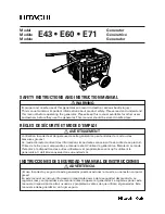
(2) On completion of the inverter analyzer diagnosis, be sure to re-crimp the FASTON terminals.
Otherwise, the terminals may be burned due to loosening.
(R15292)
Direction of crimp
FASTON terminal
This size is shortened
by the crimp.