


RZQ71~125B7V3B
Split System air conditioners
4PW16864-1A
Installation manual
8
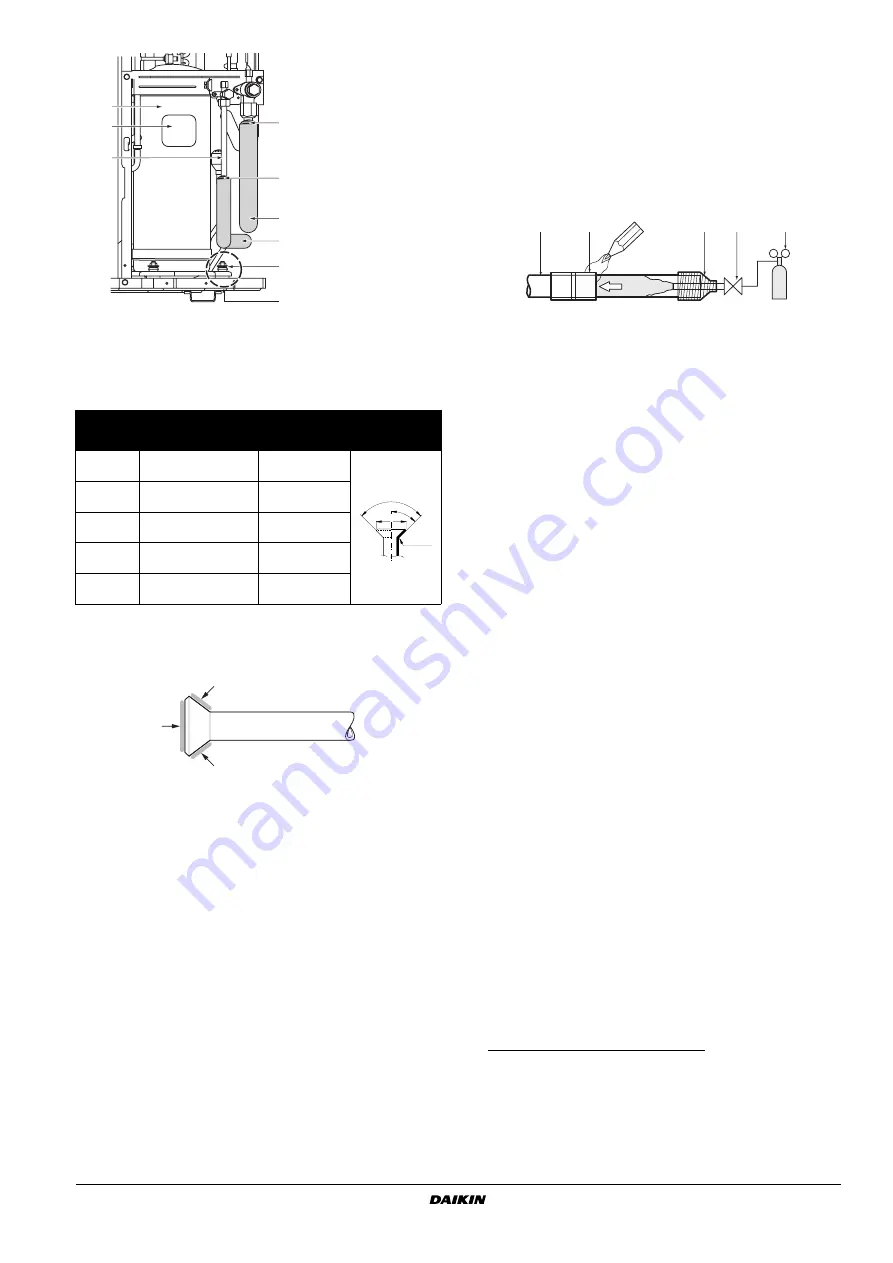
Cautions for flare connection
■
Please refer to the table for the dimensions for processing flares
and for the tightening torques. (Too much tightening will end up
in splitting of the flare.)
■
When connecting the flare nut, apply refrigerating machine oil to
the flare (inside and outside) and first screw the nut 3 or 4 turns
by hand.
Coat here with ether or ester oil.
■
After completing the installation, carry out a gas leak inspection
of the piping connections with nitrogen and such.
Cautions for necessity of a trap
Since there is fear of the oil held inside the riser piping flowing back into
the compressor when stopped and causing liquid compression
phenomenon, or cases of deterioration of oil return, it will be necessary
to provide a trap at an appropriate place in the riser gas piping.
■
Trap installation spacing.
A
Outdoor unit
B
Indoor unit
C
Gas piping
D
Liquid piping
E
Oiltrap
H
Install trap at each difference in height of 15 m.
■
A trap is not necessary when the outdoor unit is installed in a
higher position than the indoor unit.
Cautions for brazing
■
Be sure to carry out a nitrogen blow when brazing.
Brazing without carrying out nitrogen replacement or releasing
nitrogen into the piping will create large quantities of oxidized
film on the inside of the pipes, adversely affecting valves and
compressors in the refrigerating system and preventing normal
operation.
■
When brazing while inserting nitrogen into the piping, nitrogen
must be set to 0.02 MPa with a pressure-reducing valve (=just
enough so that it can be felt on the skin).
E
VACUATING
■
Do not purge the air with refrigerants. Use a vacuum pump to
vacuum the installation. No additional refrigerant is provided for
air purging.
■
Pipes inside the units were checked for leaks by the
manufacturer. The refrigerant pipes fit on site are to be checked
for leaks by the installer.
■
Confirm that the valves are firmly closed before leak test or
vacuuming.
Set up for vacuuming and leak test:
Procedure for leak test
Leak test must satisfy EN378-2.
1
Evacuate the pipes and check vacuum
(1)
. (No pressure increase
for 1 minute.)
2
Break the vacuum with a minimum of 2 bar of nitrogen. (Never
pressurize more than 4.0 MPa.)
Piping
size
Flare nut
tightening torque
A dimensions
for processing
flares (mm)
Flare shape
Ø6.4
14.2~17.2 N•m
(144~176 kgf•cm)
8.7~9.1
Ø9.5
32.7~39.9 N•m
(333~407 kgf•cm)
12.8~13.2
Ø12.7
49.5~60.3 N•m
(504~616 kgf•cm)
16.2~16.6
Ø15.9
61.8~75.4 N•m
(630~770 kgf•cm)
19.3~19.7
Ø19.1
97.2~118.6 N•m
(989.8~1208 kgf•cm)
23.6~24.0
2
1
3
5
5
A
4
4
6
1
Compressor
2
Terminal cover
3
Indoor and outdoor
field piping
4
Corking, etc.
5
Insulation material
6
Bolts
A
Be careful with pipe,
bolt and outer panel
connections
R=0.4~0.8
45
° ±
2
90
°±
0.5
A
1
Refrigerant piping
2
Part to be brazed
3
Taping
4
Hands valve
5
Pressure-reducing valve
6
Nitrogen
A
Pair system
B
Simultaneous operation system
1
Pressure gauge
2
Nitrogen
3
Refrigerant
4
Weighing machine
5
Vacuum pump
6
Stop valve
7
Main pipe
8
Branched pipes
9
Pipe branching kit (optional)
(1) Use a 2-stage vacuum pump with a non return valve which
can evacuate to –100.7 kPa (5 Torr, –755 mm Hg).
Evacuate the system from the liquid and gas pipes by using
a vacuum pump for more than 2 hours and bring the system
to –100.7 kPa. After keeping the system under that condition
for more than one hour, check if the vacuum gauge rises or
not. If it rises, the system may either contain moisture inside
or have leaks.
1
2
3
4
5
6
6


