background image

11

English

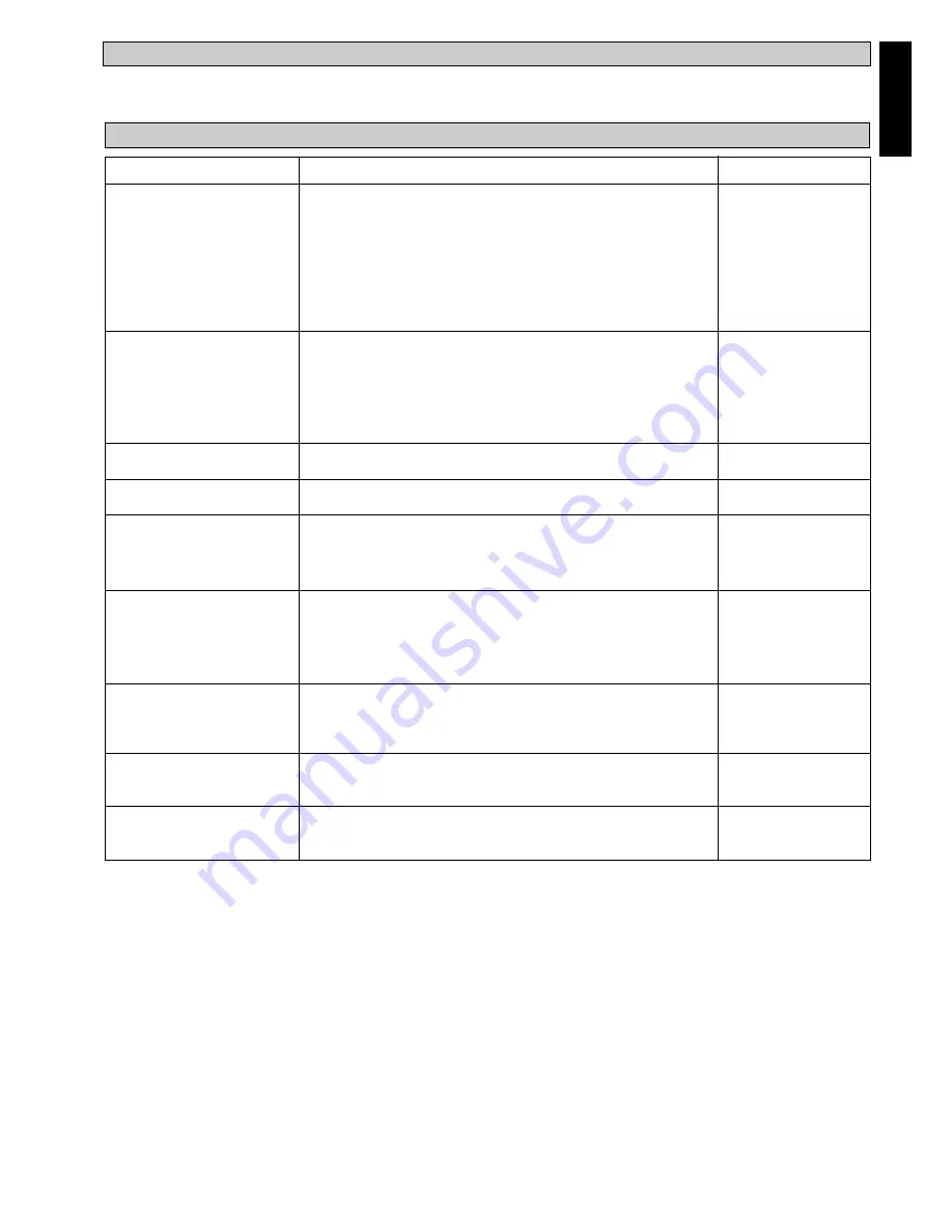
Maintenance Procedures

1. Remove any dust adhered on the filter by using a vacuum

cleaner or wash in lukewarm water (below 40°C) with neutral
cleaning detergent.

2. Rinse well and dry the filter before placing it back onto the

unit.

3. Do not use gasoline, volatile substances or chemical to clean

the filter.

1. Clean any dirt or dust on the grille or panel by wiping it using

soft cloth soaked in lukewarm water (below 40°C) with
neutral detergent solution.

2. Do not use gasoline, volatile substances or chemical to clean

the indoor unit.

1. Check its cleanliness and clean it if necessary.

1. Check for any abnormal noise.

1. Check and remove any dirt clogged between the fins.

2. Check and remove any obstacles that hinder air flowing into

and out of the indoor/outdoor unit.

1. Check the voltage and current of the indoor and outdoor unit.

2 Check the electrical wiring for any faulty contacts caused by

loose connections, foreign matters, etc. Tighten the wires onto
the terminal block if necessary.

1. No maintenance needed if the refrigerant circuit remain sealed.

However, check for any refrigerant leaks at all joints and
fitting.

1. The compressor oil is factory-precharged. It is not necessary

to add any oil if the circuit remains sealed.

1. All motor pre-lubricated and sealed at factory.

Period

At least once
every 2 week.

More frequently if
necessary.

At least once
every 2 weeks.

More frequently if
necessary.

Every 3 months.

When necessary.

Every month.

Every month.

Every 2 months.

Every 2 months.

Every 6 months.

No maintenance
required.

No maintenance
required.

Service Parts

Indoor Air Filter

Indoor Unit

Condense Drain Pan & Pipe

Indoor Fan

Indoor/Outdoor Coil

Power Supply

Compressor

Compressor Oil

Fan Motor Oil

SERVICE AND MAINTENANCE

AUTO RANDOM RE-START FUNCTION

If there is a power cut when the unit is operating, it will automatically resume the same operating mode when the power is restored.
(Applicable only to units with this feature).

Summary of Contents for RY100CV1M

Page 1: ...0CV1M RY80CV1M FDYM90CV1M FDYB90CV1M RY90CV1M FDYM90CV1M FDYB90CV1M RY90CY1M FDYM100CV1M RY100CV1M FDYM125CV1M FDYB125CV1M RY125CV1M FDYM125CV1M FDYB125CV1M RY125CY1M FDYM140CV1M FDYB140CV1M RY140CY1M...

Page 2: ...8 8 4 2 5 3 9 9 4 8 4 FDYM90CV1M 359 999 956 917 408 5 378 541 256 173 306 70 5 160 5 248 220 0 FDYB90CV1M 14 1 39 3 37 6 36 1 16 1 14 9 21 3 10 1 6 8 12 0 2 8 6 3 9 8 8 7 FDYM100CV1M 371 2 1312 1264...

Page 3: ...B C D E F G H I J K L M N O RY60CV1M 855 628 328 513 182 44 93 149 101 113 603 126 164 17 49 33 7 24 7 12 9 20 0 7 1 1 7 3 7 5 9 4 0 4 4 23 7 5 0 6 4 0 7 1 9 RY71CV1M 855 730 328 513 182 44 93 149 10...

Page 4: ...M N P RY90CV1M RY90CY1M 1030 850 400 390 414 827 72 196 91 488 448 141 5 746 5 82 RY100CV1M RY125CV1M 40 6 33 5 15 7 15 4 16 3 32 6 2 8 7 7 3 6 19 2 17 6 5 6 29 4 3 2 RY125CY1M RY140CY1M All dimensio...

Page 5: ...l A B C D E F G H J K L M N RY160CY1M 1030 850 400 448 746 5 320 25 50 85 40 141 5 20 60 40 6 33 5 15 7 17 6 29 4 12 6 1 0 2 0 3 3 1 6 5 6 0 8 2 4 All dimensions are in mm in J H C F K K B G A L E L M...

Page 6: ...OM WARNING Installation and maintenance should be performed by qualified persons who are familiar with local code and regulation and experienced with this type of appliance All field wiring must be in...

Page 7: ...allation provide clearance for servicing ease as shown in diagram and table below C mm inch D mm inch FDYM30CV1M FDYB30CV1M FDYM40CV1M FDYB40CV1M 200 500 FDYM60CV1M 7 9 19 7 FDYB60CV1M FDYM71CV1M FDYB...

Page 8: ...V1M FDYM71CV1M FDYM80CV1M Data FDYB30CV1M FDYB40CV1M FDYB60CV1M FDYB71CV1M Maximum Length Am ft 12 39 4 12 39 4 15 49 2 15 49 2 15 49 2 Maximum Elevation B m ft 5 16 4 5 16 4 8 26 2 8 26 2 8 26 2 Maxi...

Page 9: ...hips from entering the pipe Insert the flare nuts mounted on the connection parts of both indoor and outdoor unit into the copper pipes The exact length of pipe protruding from the face of the flare d...

Page 10: ...Power Supply Cable N 4WV OF COMP L N N COMP OF 4WV FDYM80CV1M RY80CV1M There must be a all pole switch with a minimum 3 mm contact gap and fuse circuit breaker as recommended in the fixed installation...

Page 11: ...There must be a all pole switch with a minimum 3 mm contact gap and fuse circuit breaker as recommended in the fixed installation circuits FDYM90CV1M FDYB90CV1M RY90CY1M FDYM125CV1M FDYB125CV1M RY125...

Page 12: ...r manifold gauge with the vacuum pump Connect the manifold gauge to the service port of the 3 ways valve Start the vacuum pump Check the low pressure manifold gauge until it indicate 0 9 bar The evacu...

Page 13: ...linder valve Disconnect the manometer and the gas cylinder Place back the service port cap Indoor FDYM30CV1M FDYM40CV1M FDYM60CV1M FDYM71CV1M FDYM80CV1M FDYB30CV1M FDYB40CV1M FDYB60CV1M FDYB71CV1M Out...

Page 14: ...he installer 1 Charging procedures Single phase compressors Evacuate the system to 500 microns Hg 67Pa To reduce evacuation time use short large diameter hoses and connect to unrestricted service port...

Page 15: ...mooth drainage of water Check that 1 Condenser fan is running with warm air blowing off the condensing unit 2 Evaporator blower is running and discharge cool air 3 The remote controller incorporates a...

Page 16: ...for any faulty contacts caused by loose connections foreign matters etc Tighten the wires onto the terminal block if necessary 1 No maintenance needed if the refrigerant circuit remain sealed However...

Page 17: ...5 Discharge air flow has bad odor 6 Condensation on the front air grille of the indoor unit 7 Water flowing out from the air conditioner unit 8 Hissing air flow sound from the air conditioner unit du...

Reviews: