

Installation manual
21
RX(Y)Q5-10-1 RXQ RXYQ
RXYHQ1 RX(Y)Q14~18P7W1BA
VRVIII System air conditioner
4PW48461-1
4
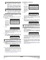
If the calculated amount of pre-charging is reached, close
valve C.
5
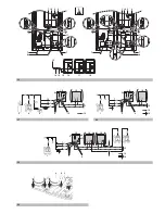
After pre-charging, perform the refrigerant charge operation as
shown below and charge the remaining refrigerant of the
additional charging amount through valve A.
(See figure 29)
1.
Start of automatic charging refrigerant
-
Open the liquid and gas side stop valves and the service port
stop valve. (Valves A, B and C must be closed.)
-
Close all frontpanels except the electric box frontpanel and
turn the power ON.
-
Make sure all indoor units are connected, refer to
"11.4. How
to check how many units are connected" on page 19
.
-
If the H2P LED is not flashing (in 12 minutes time after
turning on the power), make sure it is displayed as shown in
the
"3 Normal system display" on page 24
.
If the H2P LED is flashing, check the malfunction code on the
remote controller
"4 Remote controller malfunction code
display" on page 24
.
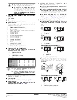
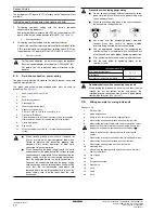
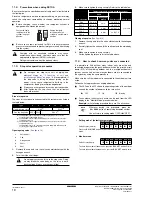
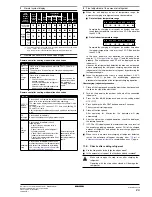
2.
Press the
button once if the LEDs combination is not
as in the figure below.
3.
Press the
button once.
4.
Hold the
button down for 5 seconds or more.
5.
Charging mode judgement
For automatic charging, the charging must be done in cooling
mode.
However, if the indoor temperature is 20°C DB or lower, in some
cases the unit will first charge in heating mode to increase the
indoor temperature.
The unit will automatically select the cooling mode or heating
mode for charging.
Continue with the automatic charging in cooling
mode OR in heating mode.
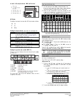
■
Charging in heating mode
(not for cooling only models)
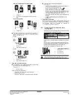
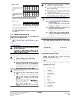
6.
Start up
Wait while the unit is preparing for charging in heating mode.
7.
Ready
Press the
button once within 5 minutes.
If the
button is not pushed within 5 minutes,
P2
will be
displayed on the remote controller. Refer to
"4 Remote controller
malfunction code display" on page 24
.
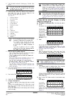
8.
Operation
When the following LED display is shown, open valve A and
close the frontpanel. If the frontpanel is left open, the system
can not operate properly during the refrigerant charging.
*
= The state of this LED is not important.
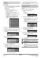
9.
Complete
If the calculated amount of refrigerant minus 10 kg is reached,
close valve A and press the
button once.
As long as the
button is not pressed, the system
will remain in heating mode. This can be required to increase the
indoor temperature.
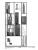
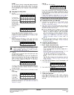
10. Press the
button to perform the temperature range
check
Out of range:
In these cases, press the
button once and follow the
procedure as
"5 Final adjustment of the amount of refrigerant"
on page 24
.
At least the unit should be charged with its original amount
of refrigerant (refer to the nameplate on the unit), before
starting the automatic charging.
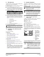
1
Measuring instrument
2
Tank (siphon system)
3
Charge hose
4
Liquid line stop valve
5
Gas line stop valve
6
Stop valve service port
7
Valve B
8
Valve C
9
Valve A
10
Outdoor unit
11
Refrigerant charge port
12
Field piping
13
Refrigerant flow
14
Indoor unit
NOTE
For a multi outdoor unit system, it is not required
to connect all charge ports to a refrigerant tank.
The refrigerant will be charged with ±22 kg in
1 hour time at an outdoor temperature of 30°C DB
or with ±6
kg at an outdoor temperature of
0°C DB.
If you need to speed up in case of a multiple
outdoor system, connect the refrigerant tanks to
each outdoor unit as shown in
figure 29
.
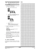
H1P
H2P
H3P
H4P
H5P
H6P
H7P
x
x w x
x
x
x
H1P
H2P
H3P
H4P
H5P
H6P
H7P
w w w w w w w
BS1 MODE
BS4 TEST
BS4 TEST
During charging in heating mode, a person must
manually close valve A before complete charging is
finished. The required amount is the the calculated
amount (see
"6.6. Example of connection" on page 9
)
minus 10 kg, therefore, the weight must be monitored
constantly.
For the cooling only models, heating mode can not be
selected. In this case, the LED display will indicate out
of range. Refer to the procedure as described in
"5 Final adjustment of the amount of refrigerant" on
page 24
.
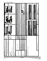
H1P
H2P
H3P
H4P
H5P
H6P
H7P
Pressure control
(for the first minute)
x c x
x
x
x w
Start up control
(for the next 2 minutes)
c c x
x
x w x
Waiting for stable
heating conditions
(for the next ±15
minutes (according to
the system))
c c x
x
x w w
H1P
H2P
H3P
H4P
H5P
H6P
H7P
c c x
x w x w
H1P
H2P
H3P
H4P
H5P
H6P
H7P
w c
*
*
*
*
*
When a malfunction occurs, check the display of the
remote controller and refer to
"4 Remote controller
malfunction code display" on page 24
.
H1P
H2P
H3P
H4P
H5P
H6P
H7P
c c c w w w w
H1P
H2P
H3P
H4P
H5P
H6P
H7P
Out of outdoor
temperture range
w c c c w x
x
Out of indoor
temperture range
w c c c x w x
BS4 TEST
BS4 TEST
BS3 RETURN
BS3 RETURN
BS4 TEST
BS1 MODE
Summary of Contents for RXYHQ12P8W1B
Page 36: ...NOTES NOTES...
Page 38: ...4PW48461 1 Copyright Daikin...