
RX(Y)Q5-10-1 RXQ RXYQ
RXYHQ1 RX(Y)Q14~18P7W1BA
VRVIII System air conditioner
4PW48461-1
Installation manual
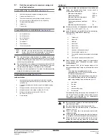
10
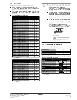
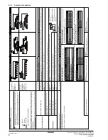
Pipe siz
e selection
F
or an outdoor unit m
ulti installation (RXYQ20~54P +
RXYHQ16~36), select the pipe siz
e in accordance with the
follo
wing figure
.
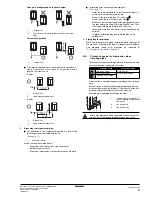
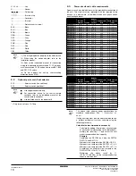
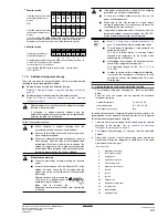
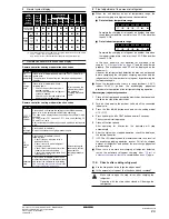
A,B,C.
Piping between outdoor unit and refrigerant branc
h kit
•
Choose from the f
ollo
wing tab
le in accordance with the outdoor unit total
capacity type
, connected do
wnstream.
Outdoor unit connection piping siz
e
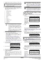
D.
Piping between refrig
erant branc
h kits
•
Choose from the f
ollo
wing tab
le in accordance with the total capacity of
all the indoor units connected below this
.
•
Do not let the connection piping e
xceed the refr
iger
ant piping siz
e
chosen b
y
gener
al system model name
.
E.
Piping between refrig
erant branc
h kit and indoor unit
•
Pipe siz
e f
or direct connection to indoor unit must be the same as the
connection siz
e of indoor unit.
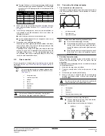
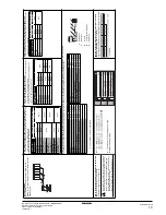
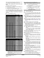
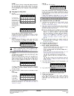
When the equiv
alent pipe length betw
een outdoor and indoor units is 90 m or more
, the siz
e of the main pipes (both gas side and
liquid side) m
ust be increased.
Depending on the length of the piping, the capacity ma
y drop
, b
ut e
v
en in such a case it is possib
le to increase the siz
e of th
e main pipes
.
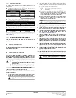
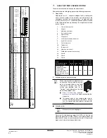
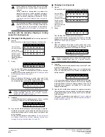
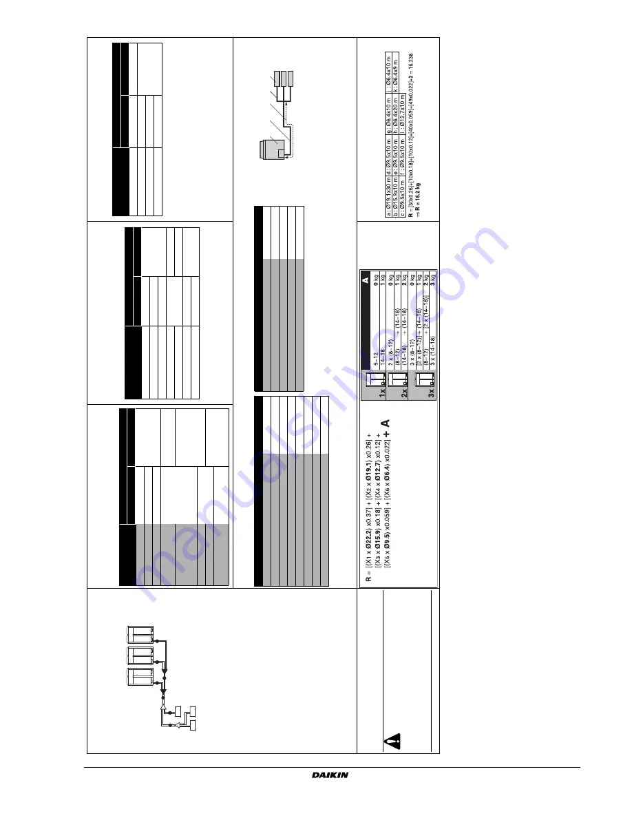
Ho
w to calculate the ad
ditional refrig
erant to be c
har
g
e
d
Additional refr
iger
ant to be charged R (kg)
R should be rounded off in units of 0.1 kg
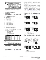
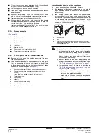
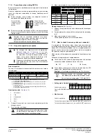
Example f
or refrig
erant branc
h using refnet joint and refnet
header f
or RXYQ34P ((1x 16) + (1x 18))
If the outdoor unit is RXYQ34P and the piping lengths are as belo
w
B
A
C
D
E
B
B
Outdoor unit
capacity type
Piping siz
e (outer diameter) (mm)
Gas pipe
Liquid pipe
RX(Y)Q5
Ø15.9
Ø9.5
RX(Y)Q8
Ø19.1
RX(Y)Q10
Ø22.2
RX(Y)Q12~16 +
16
Ø28.6
Ø12.7
RX(Y)Q18 +
22 +
RXYHQ18~22
Ø15.9
RXY(H)Q24
Ø34.9
RXY(H)Q26~34
Ø19.1
RXYQ36~54 +
RXYHQ36
Ø41.3
Indoor or outdoor unit
total capacity
Piping siz
e (outer diameter) (mm)
Gas pipe
Liquid pipe
<150
Ø15.9
Ø9.5
150
≤
x<200
Ø19.1
200
≤
x<290
Ø22.2
290
≤
x<420
Ø28.6
Ø12.7
420
≤
x<640
Ø15.9
640
≤
x<920
Ø34.9
Ø19.1
≥
920
Ø41.3
Indoor capacity type
Piping siz
e (outer diameter) (mm)
Gas pipe
Liquid pipe
20~50
Ø12.7
Ø6.4
63~125
Ø15.9
Ø9.5
200
Ø19.1
250
Ø22.2
Gas side
Liquid side
RX(Y)Q5
Ø15.9
➞
Ø19.1
RX(Y)Q5
Ø9.5
—
RX(Y)Q8
Ø19.1
➞
Ø22.2
RX(Y)Q8+10
Ø9.5
➞
Ø12.7
RX(Y)Q10
Ø22.2
➞
Ø25.4
(a)
(a)
If not a
v
ailab
le
, increase is not allo
w
e
d
RX(Y)Q12~16 + 16
Ø12.7
➞
Ø15.9
RX(Y)Q12+14 + RXYHQ12
Ø28.6
—
RX(Y)Q18 + RXYQ20~24 + RXYHQ18~24
Ø15.9
➞
Ø19.1
RX(Y)Q16+18 + 22 + RXYHQ16~22
Ø28.6
➞
Ø31.8
(a)
RXYQ26~54 + RXYHQ26~36
Ø19.1
➞
Ø22.2
RXYHQ24
Ø34.9
—
—
Increase is not allo
w
e
d
RXYQ26~34 + RXYHQ26~34
Ø34.9
➞
Ø38.1
(a)
RXYQ36~54 + RXYHQ36
Ø41.3
—
— Increase is not allo
w
e
d
1
Outdoor unit
2
Main pipes
3
Increase
4
First refr
iger
ant br
anch kit
5
Indoor unit
1
5
2
4
3
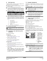
The refr
iger
ant charge of the system m
ust be less
than 100 kg.
This means that in case the calculated
refr
iger
ant charge is equal to or more than 100
kg
y
ou m
ust divide y
our m
ultiple outdoor system into
smaller independent systems
, each containing less
than 100 kg refr
iger
ant charge
.
F
or f
actor
y charge
, ref
er to the unit name plate
.
X
1...6
=
T
otal length (m) of liquid piping siz
e at
Øa
A
=
W
eight according to tab
le
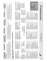
Summary of Contents for RXYHQ12P8W1B
Page 36: ...NOTES NOTES...
Page 38: ...4PW48461 1 Copyright Daikin...