INSTALLATION MANUAL
R410A Split Series
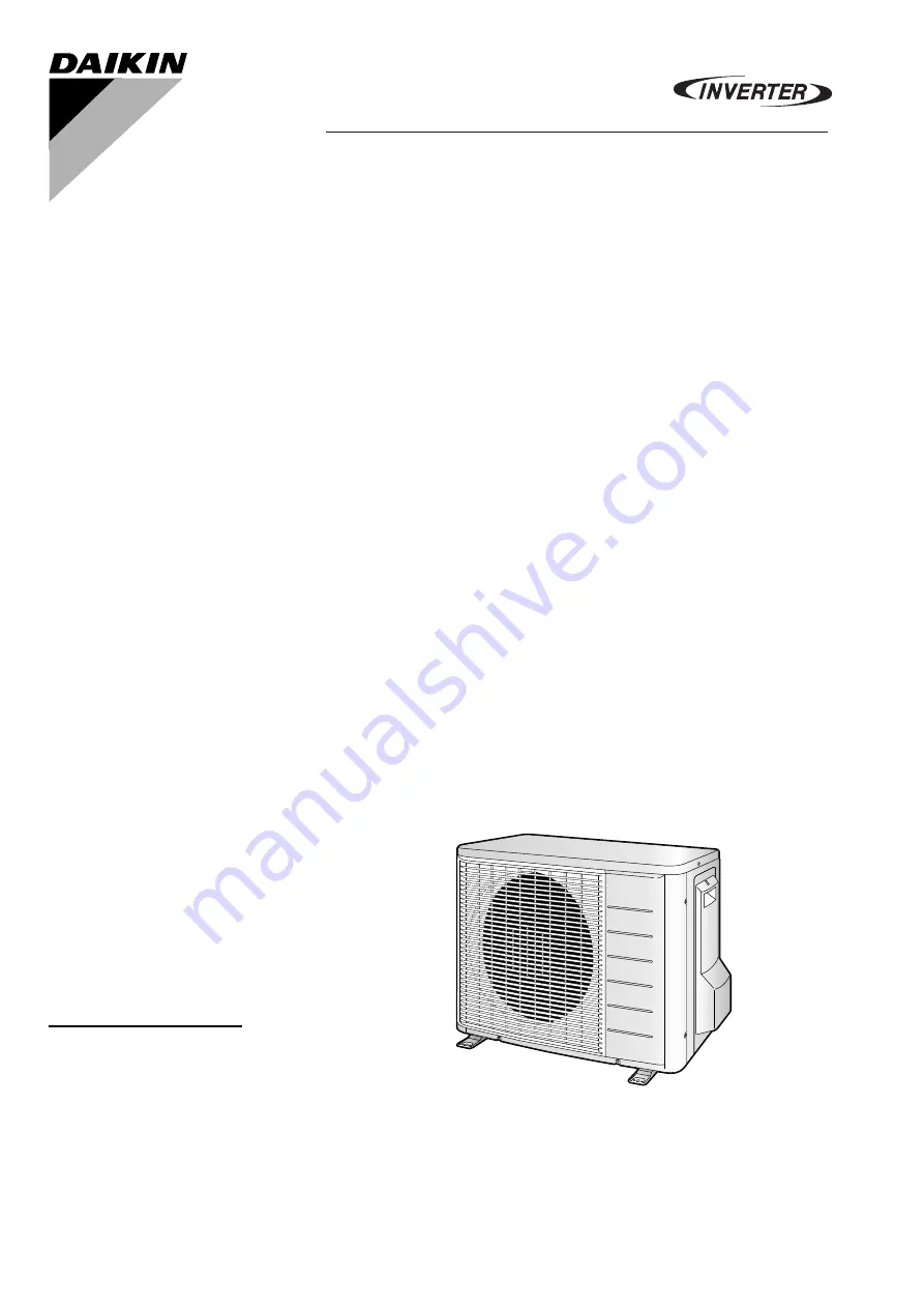
MODEL
RXLG50L2V1BRXL50K2V1BRXL50J3V1BRXLG50K3V1B
Page 1: ...INSTALLATION MANUAL R410A Split Series MODEL RXLG50L2V1B RXL50K2V1B RXL50J3V1B RXLG50K3V1B...
Page 2: ...y es valorado positivamente por B de acuerdo con el Certificado C 06 Nota delineato nel A e giudicato positivamente da B secondo l Certificato C 07 A B C 08 Nota tal como estabelecido em A e com o pa...
Page 3: ...A y es valorado positivamente por B de acuerdo con el Certificado C 06 Nota delineato nel A e giudicato positivamente da B secondo l Certificato C 07 A B C 08 Nota tal como estabelecido em A e com o p...
Page 4: ...blece en A y es valorado positivamente por B de acuerdo con el Certificado C 06 Nota delineato nel A e giudicato positivamente da B secondo l Certificato C 07 A B C 08 Nota tal como estabelecido em A...
Page 5: ...abnormal heat build up or fire When wiring the power supply and connecting the wiring between the indoor and outdoor units position the wires so that the control box lid can be securely fastened Impr...
Page 6: ...ot place under the unit anything which must be kept away from moisture NOTE Cannot be installed hanging from ceiling or stacked CAUTION When operating the air conditioner in a low outdoor ambient temp...
Page 7: ...leveled Otherwise water leakage or pooling of water may occur Foot bolt hole centres 580mm 120mm From unit s side Max allowable height Min allowable length Max allowable length 20m 1 5m 15m Liquid pi...
Page 8: ...fix the unit securely by means of the foundation bolts Prepare four sets of M8 or M10 foundation bolts nuts and washers each which are available on the market It is best to screw in the foundation bol...
Page 9: ...torque wrenches when tightening the flare nuts to prevent damage to the flare nuts and gas leakage Align the centres of both flares and tighten the flare nuts 3 or 4 turns by hand Then tighten them fu...
Page 10: ...n side of charging hose which comes from gauge manifold to gas stop valve s service port 2 Fully open gauge manifold s low pressure valve Lo and completely close its high pressure valve Hi High pressu...
Page 11: ...ng and to provide insulation dimensions as below 3 Use separate thermal insulation for gas and liquid refrigerant pipes Gas side Liquid side Gas pipe thermal insulation Liquid pipe thermal insulation...
Page 12: ...imately 15 minutes To stop the operation press the switch SW1 Wiring WARNING Do not use tapped wires stranded wires extension cords or starburst connections as they may cause overheating electrical sh...
Page 13: ...terminals on the wires up to the covered part and secure in place Ground terminal installation Use the following method when installing the round crimp style terminal CAUTION When connecting the conne...
Page 14: ...PAN HEATER Drain pan heater C7 C8 Capacitor DB1 DB3 Diode bridge FU1 FU2 FU3 FU4 FU5 Fuse FU6 Field fuse IPM Intelligent power module L Live L803 L804 Reactor M1C Compressor motor M1F Fan motor MRCW...
Page 15: ...1 3 Carry out the test operation in accordance with the operation manual to ensure that all functions and parts such as louver movement are working properly The air conditioner requires a small amoun...
Page 16: ...3P327449 5H 2013 12 Copyright 2013 Daikin...