background image

Maintenance

www.DaikinApplied.com 99 

IM 991-2 • MAVERICK II ROOFTOP

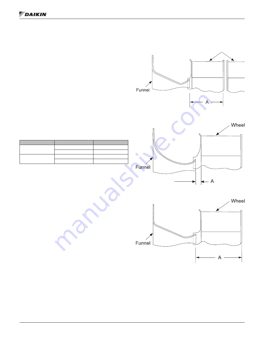
Supply Fan Wheel-to-Funnel Alignment

If the unit is equipped with an airfoil or backward curved 

supply fan, the fan wheel-to-funnel alignment must be as 

shown in 

Figure 77

Figure 78

 and 

Figure 79

 to obtain 

proper air delivery and operating clearance. If necessary, 

adjustments are made as follows: 

1. 

Verify that the fan shaft has not moved in its bearings. 

2. 

Loosen the fan hub setscrews and move the wheel(s) 

along the shaft as necessary to obtain the correct 

dimension shown in 

Table 18

3. 

Retighten the setscrews to the torque specification 

given in 

Table 17 on page 98

Tighten the setscrews 

over the keyway first; tighten those at 90 degrees to the 

keyway last. 

4. 

Verify that the radial clearance around the fan is uniform. 

Radial clearance can be adjusted by slightly loosening 

the funnel hold-down fasteners, shifting the funnel as 

required, and retightening the fasteners. 

Table 18: Wheel-to-Funnel Relationship 

Fan Type

Wheel diameter (inches)

A

DWDI Airfoil

30 

10.6 (+0.3–0.0)

33

11.7 (+0.3–0.0)

SWSI Airfoil

40

0.62

44

16.21

Figure 77: DWDI Airfoil Wheel-to-Funnel Alignment  


Figure 78: 40" SWSI Airfoil Wheel-to-Funnel Alignment   


Figure 79: 44" SWSI Airfoil Wheel-to-Funnel Alignment   


Wheels

Summary of Contents for Maverick II MPS062E

Page 1: ...tenance Manual IM 991 2 Group Applied Air Systems Part Number IM 991 Date July 2019 Maverick II Commercial Packaged Rooftop System Models MPS062E MPS075E 62 through 75 Tons R 410A Refrigerant MicroTec...

Page 2: ...ntrol Actuators 56 Convenience Receptacle 56 Enthalpy Control 57 Smoke and Fire Protection 58 External Time Clock 59 Field Output Signals 60 Variable Frequency Drive Operation 61 Optional Low Ambient...

Page 3: ...ol box door It includes the unit model number serial number unit part number electrical characteristics and refrigerant charge Compressor Nameplate Size 62 units utilize the tandem compressor design E...

Page 4: ...tric heat unit with the locations of the major components Figure 3 on page 5 shows a typical cooling only unit with the locations of the major components These figures are for general information only...

Page 5: ...Introduction www DaikinApplied com 5 IM 991 2 MAVERICK II ROOFTOP Figure 3 Typical Component Locations for Cooling Only Unit 1 5 NPT drain...

Page 6: ...gure 4 Circuit Schematic Figure 5 Condenser Piping Scroll Compressors Two to Three Compressors per Circuit are Provided 6 Compressors Shown B A J D L K M C H F I E E A Compressor 2 or 3 per circuit B...

Page 7: ...OP Figure 6 Air Handler Piping Flat DX Figure 7 Air Handler Piping Staggered DX Legend 1 Thermostatic expansion valve 2 Distributor 3 Hot gas bypass line Liq u id lin e so len o id valve 3 Legend 1 Th...

Page 8: ...wiring diagram the various control components mounted throughout the units legend which is included in Wiring Diagrams on page 40 See Control Panel on page 10 for the locations of control Figure 8 Co...

Page 9: ...s Cooling Only and Hot Water HeatUnits Economizer Filter DX Heat section Supply fan discharge plenum section Condenser RAT SD2 RAE ACT3 PC5 OAE VM1 DAT OAT optional HP3 4 optional HTR3 4 optional sect...

Page 10: ...locations are shown in the from these figures depending on the particular unit options following figures These figures show a typical unit See Wiring Diagrams on page 40 for the legend and configurati...

Page 11: ...Introduction www DaikinApplied com 11 IM 991 2 MAVERICK II ROOFTOP Figure 11 Typical Main Control Panel 460 Volt...

Page 12: ...FTOP 12 www DaikinApplied com Introduction Figure 12 Typical Gas Heat Panel Figure 13 Typical Prop Exhaust Panel 2 Fans 460 Volt Figure 14 Condensing Unit Control Panel S3 FSG FSG Time LS1 LS2 AS IT T...

Page 13: ...l Figure 16 Harness Plug Connector Detail GLG3 DS3 M41 M43 FB41 FB42 FB43 H53 TB11 M31 M32 M33 FB31 FB32 FB33 M42 LT OP1 LT OP2 LT11 LT10 COMP6 COMP5 COMP3 COMP4 COMP1 COMP2 DFRH DFLH OPEN4 SD1 SD2 GS...

Page 14: ...ections for sequence of operation for condenser fans with Fantrol Table 2 R 410A Fantrol Setpoints in F with MicroTech III Controls MPS Model Degrees Farenheit B05 B06 B07 B08 PC13 PC23 Setpoint Diffe...

Page 15: ...sible for assuring the condensing section is not exposed to excessive wind or air recirculation Receiving Inspection When the equipment is received all items should be carefully checked against the bi...

Page 16: ...near exhaust vents or other sources of contaminated air If the unit is installed where windy conditions are common install wind screens around the unit maintaining the clearances specified see Figure...

Page 17: ...te drain side of the unit be no higher than the opposite side Assembly of a typical roof curb is shown in Figure 19 on page 18 Parts A through K are common to all units having bottom supply and return...

Page 18: ...rb and condensing section support are not equal Cap 1595 mm 2159 mm 87 0 2210 mm 3 5 89 mm 8 8 224 mm 38 0 965 mm 38 8 986 mm 2 0 51 mm 7 5 191 mm 28 0 711 mm 6 8 173 mm 1 5 38 mm 76 0 1930 mm Inside...

Page 19: ...163 mm See Detail B 81 0 2057 mm 7 5 191 mm 28 0 711 mm 1 5 25 mm 8 8 223 mm OPNG 2 Typ 1 5 25 mm 4 Typ 38 0 965 mm OPNG RA SA 6 8 173 mm 87 0 2210 mm 1 5 25 mm 8 0 203 mm 61 0 1549 mm MPS 062E only o...

Page 20: ...from the bracket to the hook should always be longer than the distance between the outer lifting points If the unit is stored at the construction site for an intermediate period take these additional...

Page 21: ...il length of the units NOTE Z excludes hoods and overhung parts extending past base rails of the unit Installation A Z X Y If A 288 4 point lift is sufficient If A 288 6 point lift is required B A 2 4...

Page 22: ...r metal to protect the roof against possible damage If condensate is piped into the building drainage system pitch the drain line away from the unit a minimum of 1 8 per foot The drain line must penet...

Page 23: ...an guarantee a 100 safeguard against coil freeze up Glycol solutions or brines are the only freeze safe media for operation of water coils at low entering air temperature conditions When no factory pi...

Page 24: ...n The damper is set so that the crankarm moves through a 90 degree angle to bring the economizer dampers from full open to full close see Figure 27 Access to the actuator and linkage is from the fille...

Page 25: ...on the damper setting This setting is made at the linkage rod on units with manually adjustable linkages On units provided with MicroTech III controls the damper position may be set at the controller...

Page 26: ...duct opening Do not support the total weight of the ductwork from the unit or these duct flanges See Figure 29 Units with optional back return or side discharge all have duct collars provided To expo...

Page 27: ...4 Locate the duct tap in a non turbulent flow area of the duct Keep it several duct diameters away from take off points bends neckdowns attenuators vanes or other irregularities 5 Use a static pressu...

Page 28: ...fitting for sensor SPS2 5 Locate the reference pressure LO tap on the roof Keep it away from the condenser fans walls or anything else that may cause air turbulence Mount it high enough above the roof...

Page 29: ...late All units are provided with internal power wiring for single or dual point power connection The power block or an optional disconnect switch is located within the main control panel Field power l...

Page 30: ...IM 991 2 MAVERICK II ROOFTOP 30 www DaikinApplied com Electrical Installation Figure 34 Typical Power Wire Entrance Unit View Actual Opening Shown on Submittal Documents...

Page 31: ...or power block Size grounding conductor in accordance with Table 250 95 of the National Electrical Code In compliance with the National Electrical Code an electrically isolated 115V circuit is provide...

Page 32: ...to the unit wiring diagrams for additional installation information Wiring must comply with applicable codes and ordinances The warranty is voided if wiring is not in accordance with these specificati...

Page 33: ...th can occur CAUTION Do no use impact tools for field spring mount adjustments as damage to bits or to the bolt slot may occur To adjust spring mount compression perform the following 1 Loosen the 0 6...

Page 34: ...etween the flanges of the neoprene center bumper This results in 0 25 6 mm clearance in all directions When the fan is turned OFF the restrainer angle may come to rest on the neoprene center bumper Th...

Page 35: ...actory installed jumpers between TB2 101 and 105 and between 101 and 106 Fan Operation A supply fan is provided on every unit That may be the only fan but either a return fan or an exhaust fan or fans...

Page 36: ...half the Occupied or Unoccupied Cooling Dead Band The unit will also transition from the Cooling to Fan only operating state if Cooling operation is disabled due to OA ambient lockout Staging DAT Cont...

Page 37: ...d the leaving coil temperature is less than the minimum leaving coil setpoint Average Discharge Control Method Illustration Figure 42 on page 38 is an illustration of the Degree Time compressor stagin...

Page 38: ...lapsed time since the last stage change in this illustration is 11 0 minutes Point 8 The Cooling Interstage Timer has expired Since the discharge air temperature is still above the Effective Discharge...

Page 39: ...s the Projected Control Temperature used to turn on and off stages of heating and cooling for Zone Control units It is not used in DAT Control units In Zone Control cooling and heating operation the P...

Page 40: ...ntrol box HS3 Heat switch electric heat deadfront interlock Electric heat box ID Description Standard Location HTR1 6 Crankcase heaters On compressors IT Ignition transformer Gas heat box LAT Leaving...

Page 41: ...ine 115 V ac Main control box T2 Transformer control input 115 24 V ac Main control box T3 Transformer control output 115 24 V ac Main control box T4 Transformer exh damper actuator 115 12 V dc Main c...

Page 42: ...IM 991 2 MAVERICK II ROOFTOP 42 www DaikinApplied com Wiring Diagrams Figure 43 VAV Fan Power Unit Powered Receptacle...

Page 43: ...Wiring Diagrams www DaikinApplied com 43 IM 991 2 MAVERICK II ROOFTOP Figure 43 continued VAV Fan Power Unit Powered Receptacle...

Page 44: ...109 426 MTR T3 T2 T1 T3B T3A T2B T2A T1B T1A L3B L3A L2B L2A L1B L1A T3 T2 L3 L2 T1 L1 G T3 T2 T1 L3 L2 L1 L3B L3A L2B L2A L1B L1A L3 3 L2 3 L1 3 SUPPLY FAN MMP10 M10 GLG1 DS1 PB11 PB11 111A 110A 109A...

Page 45: ...Wiring Diagrams www DaikinApplied com 45 IM 991 2 MAVERICK II ROOFTOP Figure 45 MPS 070 Condensing Unit Power...

Page 46: ...IM 991 2 MAVERICK II ROOFTOP 46 www DaikinApplied com Wiring Diagrams Figure 46 VFD Control...

Page 47: ...Wiring Diagrams www DaikinApplied com 47 IM 991 2 MAVERICK II ROOFTOP Figure 47 VAV Control Inputs...

Page 48: ...IM 991 2 MAVERICK II ROOFTOP 48 www DaikinApplied com Wiring Diagrams Figure 47 continued VAV Control Inputs...

Page 49: ...Wiring Diagrams www DaikinApplied com 49 IM 991 2 MAVERICK II ROOFTOP Figure 48 Gas Burner Control...

Page 50: ...IM 991 2 MAVERICK II ROOFTOP 50 www DaikinApplied com Wiring Diagrams Figure 48 continued Gas Burner Control...

Page 51: ...Wiring Diagrams www DaikinApplied com 51 IM 991 2 MAVERICK II ROOFTOP Figure 49 Electric Heat Control...

Page 52: ...IM 991 2 MAVERICK II ROOFTOP 52 www DaikinApplied com Wiring Diagrams Figure 49 continued Electric Heat Control...

Page 53: ...Wiring Diagrams www DaikinApplied com 53 IM 991 2 MAVERICK II ROOFTOP Figure 50 Condensing Unit Control with Scroll Compressors...

Page 54: ...IM 991 2 MAVERICK II ROOFTOP 54 www DaikinApplied com Wiring Diagrams Figure 50 continued Condensing Unit Control with Scroll Compressors...

Page 55: ...AN 207 jprs 24V SRC MCB 1 1NO BO1 SUPPLY FAN 207 SRC 9 16 MCB 207 11 31 MMP10 12 32 11 31 MMP20 12 32 TO MOTHERBOARD WIRED INTERNAL SOURCE 9 16 T3_COM 3 11 T3_24V 3 11 115VAC_GF 1 T1_N 1 68 FIELD SUPP...

Page 56: ...are used for the 0 30 outdoor air and economizer dampers The mixing dampers are normally closed to the outside air Convenience Receptacle A Ground Fault Circuit Interrupter GFCI convenience receptacl...

Page 57: ...ntake position by the MicroTech III controller Table 5 Enthalpy Control Settings Control curve Control point temperature at 50 RH A 73 F 23 C B 70 F 21 C C 67 F 19 C D 63 F 17 C Differential Enthalpy...

Page 58: ...ble for meeting all local and NFPA building code requirements with respect to smoke fume and fire control Factory installed smoke detectors have similar wiring and the control sequence is as follows W...

Page 59: ...ernal Time Clock or Tenant Override There are several methods of switching the rooftop unit between occupied and unoccupied operation It can be done by the controller internal schedule a network sched...

Page 60: ...se this signal wire the coil of a field supplied and installed 24V ac pilot relay across terminals 116 and 117 on TB2 When this output is ON 24 V ac is supplied from the T3 control transformer through...

Page 61: ...ormation clearing alarms OM 920 Duct High Pressure Limit The duct high pressure limit control DHL is provided on all VAV units The DHL protects the duct work the terminal boxes and the unit from over...

Page 62: ...and varies the condenser fan speed accordingly The pressure transducer is calibrated to provide a 1 0 to 5 0V dc signal with a 8 to 30 V dc input starting at 1 0 V dc 250 psig and up to 5 0 V dc 400...

Page 63: ...tion decal affixed to the unit or as shown in Figure 61 For three phase installations fan rotation can be reversed by simply interchanging any two of the three electrical leads The adjustable motor pu...

Page 64: ...the length of the mounting bracket slot Figure 62 will effect the full open balance of the blade assembly Moving the weights further away from the blade pivot point will cause the blades to become mo...

Page 65: ...lowest tension at which the belts will not slip at peak load conditions For initial tensioning the proper belt deflection half way between pulley centers is 1 64 for each inch of belt span For example...

Page 66: ...Increase fan speed Excessive dirt on propeller Clean propeller ExcessiveNoise Bearings Tighten bearing collars and setscrews Lubricate bearings Replace defective bearings V Belt drive Tighten pulleys...

Page 67: ...arings for bearing lubrication Many fractional horsepower motors installed on the smaller fans are lubricated for life and require no further attention Oil motors equipped with oil holes in accordance...

Page 68: ...bris is removed and that the filters are clean 3 Verify that all electrical work is complete and properly terminated 4 Verify that all electrical connections in the unit control panel and compressor t...

Page 69: ...3 14 linear stroke to open it fully Do not allow dampers to be driven beyond their normal full closed or full open position 1 Check whether the outdoor air is suitable for free cooling by displaying...

Page 70: ...el is louder and current draw is reduced substantially After several minutes of operation the compressor s motor protector trips All three phase compressors are wired the same internally Therefore onc...

Page 71: ...ps 2 through 9 substituting circuit 2 nomenclature for circuit 1 nomenclature CS2 TD2 CCB2 and compressor 2 and 4 13 Check the compressor oil level again add oil if low 14 Verify that the condenser re...

Page 72: ...pen the valve to the coil The three way hot water valve is open to the coil when the valve stem is down If the unit loses power the spring in the actuator should drive the valve wide open to the coil...

Page 73: ...on at which the belt will not slip under peak load conditions 2 Check tension frequently during the first 24 48 hours of operation 3 Over tensioning shortens belt and bearing life 4 Keep belts free fr...

Page 74: ...is key projects a small amount to provide a grip for removing 3 Adjust the sheave pitch diameter for the desired fan speed by opening the moving parts by half or full turns from closed position Do not...

Page 75: ...y Adjusting 1 Slack off all belt tension by moving the motor toward the driven shaft until the belts are free from the grooves For easiest adjustment remove the belts 2 Loosen setscrews D 3 Loosen but...

Page 76: ...outer locking ring down until it touches the inner locking ring Then back off the outer ring 1 2 to 3 4 turn until the inner and outer ring screw holes line up Reinsert locking screws A but do not ti...

Page 77: ...x RF SF Max Sup Fan Min RF SF Min 11 Set the economizer control parameters as required in keypad menu Main Menu View Set Unit Economizer OAD Econo Pos 12 Set the control timers as required in keypad m...

Page 78: ...he line contains a changeable value and the cursor is at that line the entire line is highlighted Each line on a page may also be defined as a jump line meaning pushing the navigation wheel will cause...

Page 79: ...om 3 to 30 minutes via the Timer Settings menu in the Extended Menus Figure 74 Password Main Page Figure 75 Password Entry Page Navigation Mode In the Navigation Mode when a line on a page contains no...

Page 80: ...MinOAFlw Spt 2000CFM Occ Htg Spt 68 0 F OA Temp XXX F Disch Air XXX F EW Temp XXX F Rel Humidity XXX About This Unit SO_Item 123456_12345 Unit SN FBOU123456789 App Version 2506017xxx Cf1 15 xxxxxxxxx...

Page 81: ...Valve Off Comp 7 Off ERec Wheel Off Comp 8 Off ER Whl Cmd 0 U1 Comp 1 Off ERBP Dmpr Cl Off U1 Comp 2 Off ERBP Dmpr Op Off U2 Comp 1 Off Cond Wtr Pump Off U2 Comp 2 Off Alm Output Off Cond Sol 1 Off F...

Page 82: ...p XXX F EW Temp XXX F Mixed Air XXX F ER LAT XXX F ER EAT XXX F Sump Temp XXX F PA Temp XXX F DRT1 XXX F DRT2 XXX F DRT3 XXX F SRT XXX F DFT XXX F IRT XXX F ORT XXX F INVCompTemp XXX F Occupancy Occup...

Page 83: ...MDD YY HH MM OPTIMAL START Enable No Htg Range 0 4 F min Htg OAT 35 F Des Htg OAT 0 F Clg Rate 0 4 F min Clg OAT 85 F Des Clg OAT 95 F DAYLIGHT SAVINGS DLS Strt Mon Mar DLS Strt Wk 2nd Week DLS End Mo...

Page 84: ...600 Duct Press 1 X Xin V A Min CFM 0V ECM Status __________ Duct Press 2 X Xin V A Max CFM 10 V 1 ZONE VAV CONTROL SAF CFM DB 3 Min Clg Spd 40 SAF CFM Period 30s Max Clg Spd 100 SAF CFM Gain 0 1 Min H...

Page 85: ...2s ExhMxOAPos 100 Max Spd Chg 4 Exh Stg 1 On 40 Sup Fan Max 100 Exh Stg 1 Off 30 RF SF Max 95 Exh Stg 2 On 55 Sup Fan Min 30 Exh Stg 2 Off 40 RF SF Min 25 Exh Stg 3 On 70 Lo Fan Diff 75 Exh Stg 3 Off...

Page 86: ...R22 Air Flw Ing 120s Sens Alm Dly 30s Temp AlmDly 30s ALARM CONFIG Emerg Stop ManClr Exp Valve Set Up EXP VALVE STATUS EXP VALVE SETUP EVI Pos XXX SSH DB 2 0 F EVO Pos XXX SH Lo Base 6 0 F 5 0 F 2 0 F...

Page 87: ...EAT XXX F Min ExhT Diff 2 0 F Max ExhT Diff 6 0 F ER Whl Stg Tm 5min ER Whl Off Tm 20min Rel Humidity XXX Min Whl Spd 5 Intersect Pt XXX X F Fst Mgnt Meth Timed OA Frst Temp 20 56 F Defrost Time 5min...

Page 88: ...Alarm 1 Alarm Type Alarm 2 Alarm Type Alarm 10 Alarm Type Save Restore Set tings Save Params No Rstr Params No Rstr Factory No SaveToCard No LoadFromCard No CreateTrace No Trace To SD No Service Menu...

Page 89: ...Input Status MCB DI1 ____________ MCB DI2 ____________ MCB DI3 ____________ MCB DI4 ____________ MCB DI5 ____________ MCB DI6 ____________ EMD DLA1 __________ Digital Output Status MCB DO1 __________...

Page 90: ...0 0 F Return Air 0 0 F Space Temp 0 0 F OA Temp 0 0 F EF LC Temp 0 0 F EW Temp 0 0 F Mixed Air 0 0 F MAT LON SCC 0 0 F ER LAT 0 0 F ER EAT 0 0 F Sump Temp 0 0 F DRT1 0 0 F DRT3 0 0 F SRT 0 0 F DFT 0...

Page 91: ...IFB Comm Status IFB SW Vers VP0329008 IFBCommStatus ____ PrvCommStatus _______ MM DD YYYY HH MM SS ACS1 DataRcvd _______ ACS3 DataRcvd _______ Fault Code Details ACTIVE FAULT CODES INVAlarmCode _____...

Page 92: ...nce Name Min OA Reset None Apply Changes No HEAT COOLCHANGEOVER Ctrl Temp SRC RAT AplyTstatChg No Use Tstat Spt No Occ Clg Spt 72 F Occ Htg Spt 68 F FAN CONTROL OPTIONS SAF Ctlr DSP RF EF Ctlr Trackin...

Page 93: ...ting time and the indoor and outdoor environmental conditions Routine maintenance should cover the following items Tighten all belts wire connections and setscrews Clean the evaporator and condenser c...

Page 94: ...ts The steps below are necessary only if the unit has been started 1 Turn the compressor manual motor protectors MMP to the OFF position 2 Close the discharge and liquid line refrigerant service valve...

Page 95: ...of water Table 7 Approximate R 410A Refrigerant Charge per Circuit Unit size Base charge lbs per circuit less DX coil DX coil charge lbs per circuit per coil row Blow through RPS RDT or draw through R...

Page 96: ...erating charge per circuit on the unit nameplate for future reference Carefully add refrigerant slowly enough to the suction to prevent damage when first adding charge to the suction Adjust the chargi...

Page 97: ...od quality lithium or lithium complex base grease using mineral oil conforming to NLGI grade 2 consistency and an oil viscosity of 455 1135 SUS at 100 F 100 200 cSt at 40 C may be used for relubricati...

Page 98: ...ousing temperature typical applications operate at 100 F 105 F 38 C 66 C Tighten all locking devices after 500 hours or 3months whichever comes first Vibration Levels Each unit as shipped is trim bala...

Page 99: ...t dimension shown in Table 18 3 Retighten the setscrews to the torque specification given in Table 17 on page 98 Tighten the setscrews over the keyway first tighten those at 90 degrees to the keyway l...

Page 100: ...discharge tubes Make the cuts in the straight portions of the replacement tubes and as near the compressor as possible 4 Braze couplings on the cut end of the original tubes so that they fit snugly i...

Page 101: ...tion Connecting the Condenser Coil to Copper Tubing Figure 85 and Figure 86 show the aluminum condenser coil connection s to the copper tubing in the unit Because of the low melting point of aluminum...

Page 102: ...the liquid line shut off valve The port is intended for connecting to a suitable and approved storage container while using the unit compressor s to pump liquid refrigerant into a storage container S...

Page 103: ...manual reset is mounted alongside of each MMP as a means to differentiate between a short circuit and overload trip conditions The MMP trip points are factory set Do not change unless the motor ampaci...

Page 104: ...ms options Screw type spring loaded and ring cable lug connection Switch position indicator to indicate a trip and TEST function for wiring Large rotary button to adjust current to Motor RLA Selector...

Page 105: ...deactivated after a specified trip delay Trip Delay The output relay reactivates after power line conditions return to an acceptable level for a specified amount of time Restart Delay The trip and re...

Page 106: ...ect is a molded case switch with similar features of the circuit breaker The through the door feature provides a safety interlock that disables power when the control panel door is opened Opening the...

Page 107: ...ure Also check for faulty wiring connections at the VFD analog inputs The controller displays and controls to the lower of the two readings If a sensor is defective and inputs 0 volts to the VFD the s...

Page 108: ...ble 150 CM 193408801 MT3 Local HMI Cable 80 CM 193408901 MT3 Local HMI Cable 150 CM 193409001 MT3 Real Time Clock Battery 200 Days 193409101 MT3 Conn Set CTRL Spring Top Entry 193409201 MT3 Conn Set E...

Page 109: ...ed portion of the trio may need replacement Replacing a Portion of a Tandem or Trio The decision to replace the failed portion of the tandem or trio as opposed to replacing the entire tandem or trio m...

Page 110: ...nd the compressor If the compressor is not returned you will be billed for the replacement compressor 5 Consideration may be given at this time to a compressor teardown analysis depending on the histo...

Page 111: ...termination and this warranty shall expire twelve 12 months from that date Exceptions 1 If free warranty labor is available as set forth above such free labor does not include diagnostic visits inspec...

Page 112: ...______ State _________________________________ Name of person doing start up ____________________________________________________________________________________ Company name _________________________...

Page 113: ...ase heaters operating and have they been operating 24 hours prior to start up Yes No N A J Are all electrical power connections tight Check compressorelectrical box Yes No N A K Is the condensate drai...

Page 114: ...Phase 1________ Phase 2 ________ Phase 3 _______ Compressor 6 Phase 1________ Phase 2 ________ Phase 3 _______ C Low pressure cut out Circuit 1 __________ psig Circuit 2 __________ psig D Low pressure...

Page 115: ...draw across each phase at each heating stage Stage 1 Stage 2 Stage 3 Stage 4 Stage 5 Stage 6 Phase L1 ___________ ____________ ____________ ___________ ___________ ____________ Phase L2 ___________ _...

Page 116: ..._ in Wc 75 ______ in Wc 100 ______ in Wc 100 ______ in Wc VII Hot Water Coil A Pressure test OK Yes No N A VIII Heat Recovery A Heat wheel rotates freely Yes No N A B Heat wheel VFD operates properly...

Page 117: ...bleshooting of the system operation and facilitates restoration after a controller replacement Thank you for completing this form Please sign and date below Signature _________________________________...

Page 118: ...______________________________________________________ 2 How would you rate the overall appearance of the product i e paint fin damage etc Excellent Good Fair Poor 3 Did all sections of the unit fit t...

Page 119: ......

Page 120: ...nt to its standard terms and conditions of sale including Limited Product Warranty Consult your local Daikin Applied Representative for warranty details To find your local Daikin Applied Representativ...

Reviews: