background image

OM 1077-1 • MAVERICK I 44 www.DaikinApplied.com

W

IrIng

 d

IagraMs

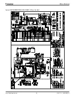
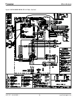
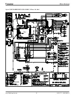
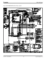
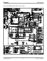
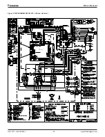
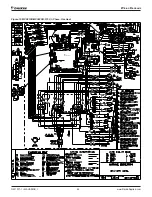
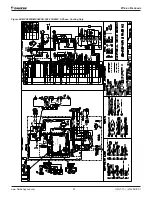
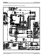
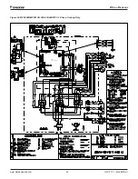
Figure 21: 

MPS006B-MPS007B, 208-230/460/575V, 3-Phase, Cooling Only    


DDC 
Controller

Summary of Contents for Maverick I

Page 1: ...lied Air Systems Part Number OM 1077 Date July 2016 Maverick I Package Air Conditioner DDC Rooftop Unit Controller Heating Cooling Gas Electric and Electric Electric Models MPS 003B 025B 3 to 25 Tonns...

Page 2: ...e Multi conductor Wire 9 Stand Alone with Thermostat 10 Standalone with Zone Sensor and Time Clock 10 Standalone with Building Automation System 11 Indoor Relative Humidity Sensor 12 Sequence of Opera...

Page 3: ...nce at their own expense The Maverick I 3 to 25 ton Package has a Rooftop Unit Controller factory mounted and wired in their respective control panel The DDC Controller is a solid state microprocessor...

Page 4: ...l minimum position set point local or remote power exhaust set point CO2 set point CO2 and outdoor enthalpy sensor if selected to control dampers to an accuracy of 5 of stroke The actuator is spring r...

Page 5: ...set unit type P12 Test Pins to force defrost for heat pump models P13 Connector to Integrated Furnace Control IFC provides power and communication between DDC Controller and IFC T7 Field Installed Spa...

Page 6: ...e the building zone temperature Sensors should be located on an interior building wall 2 RAT Return Air Temperature The DDC Controller has a return air temperature input This input is used to monitor...

Page 7: ...tect smoke due to fire in the air condition or ventilation ducts 20 FP Fan proving The unit mounted fan proving switch monitors the pressure differential across the unit blower to detect when the indo...

Page 8: ...hermostat Wall mounted sensor with space point adjustment 113117701 18 3 Solid 18 AWG 3 C CL2P Thermostat Control Output Descriptions 1 CC1 Compressor output 1 The DDC Controller can control the compr...

Page 9: ...unit and Use copper conductors unless otherwise specified Ensure that the AC control wiring between the controls and the unit s termination point does not exceed three 3 ohms per conductor for the len...

Page 10: ...uts and Outputs Standalone with Zone Sensor and Time Clock If Occupied Mode is set to any of the options other than Off and Control By Thermostat the control will operate in Stand Alone mode or networ...

Page 11: ...nd Alone mode or network using its local temperature sensors to determine demand The system can be set up with a zone sensor 910108514 or 910108214 communication card and 2nd party building automation...

Page 12: ...door relative humidity sensor to operate the optional hot gas reheat coil Because this is a powered sensor an additional wire to the 24Vac power supply from the unit is required The R thermostat input...

Page 13: ...ontroller will utilize heat sources in the following order of priority as available Gas Heat and Electric When the heat demand requires multiple heating outputs at the same time a minimum staging dela...

Page 14: ...monitored to ensure limit rollout and pressure switches are closed flame is established and the thermostat call for heat remains Low gas low inducer and blower remain energized If the DDC Controller c...

Page 15: ...urn to steady on and the IFC will begin a pre purge time with high gas output energized to begin a re ignition attempt The indoor blower remains on for the delay OFF time through the re ignition attem...

Page 16: ...sed when it should be open and has not de energized after the inducer was shut off for 15 seconds then both inducers are re energized to vent the unburned gas Soft Lockout The IFC shall not initiate a...

Page 17: ...please see the appropriate sections and have a full understanding of what you are changing Adjustment are possible only when a blinking cursor is over or next to the parameter to be adjusted The blink...

Page 18: ...Ext DCV Level Eff DCV Level Dff Eco Position Eff Min Position Furnace Ctrl Device ID IFC Fault IFC Inputs IFC Outputs Time Delays Demand Delay Indr FanOn Dly Indr Fan Off Dly Keypad Tmr Lim Compresso...

Page 19: ...ows the details of existing alarms The option for system configuration is set with a configuration key from the factory Unit Status Screen The status screen shows basic information about the operation...

Page 20: ...Mode is a state in which the control utilizes occupied set points for a limited amount of time after which it returns to unoccupied mode To start Tenant Override the user presses a button on the spac...

Page 21: ...perature of comfort The user has two ways to adjust the set point a using the User interface or b sending a command through the network The set point selection will only be valid when the board is not...

Page 22: ...information available from the Economizer When this device is not connected the control will show the word Unavailable on the second line of the display The Economizer uses controllable dampers to inc...

Page 23: ...Limit The ventilation limit corresponds to a minimum position of the Economizer that complies with the minimum acceptable outside air ventilation rate The volumetric flow rate of outside air required...

Page 24: ...value DDC Controller sends to the Economizer Effective DCV Level This is the actual DCV Level in ppm Effective Economizer Position This is the actual position of the economizer Effective Minimum Posi...

Page 25: ...r de energizes CMRT Compressor Minimum Run Time The compressor minimum run time is an adjustable time used to ensure proper compressor oil return Stage Delay The stage delay is an adjustable time that...

Page 26: ...um of ten alarms can be displayed Humidity Control This screen allows a indoor relative humidity sensor connected to the field configurable input 2 on the DDC control to monitor and control the indoor...

Page 27: ...network Y2 Second stage cooling call from thermostat or network Table 15 Units with Two Stage Cooling Mode Compressor1 Compressor2 Indoor Fan Notes Low Reheat Reheat OFF 1st Stage Cool Speed Operates...

Page 28: ...f the full speed that the indoor fan is commanded to run when a Fan Only call is given by the building manager network if connected or the room thermostat The Low Fan Speed can be adjusted between 50...

Page 29: ...erature from reaching extreme values Compressor contactor has failed closed Thermostat demand signal not connected to module Low Voltage Circuit 1 CA1 Comfort Alert Code 9 Shutdown and wait for voltag...

Page 30: ...tdown Low line voltage Excessive Refrigerant in compressor Seized bearings in compressor Open Circuit 2 CA2 Comfort Alert Code 5 Circuit 2 shutdown and retry after Anti Short Cycle Delay ASCD Note Thi...

Page 31: ...oller When the outdoor temperature drops below the cooling lockout temperature set point the unit will prevent the compressor from operating in cool mode Selectable range is between 30 F and 50 F with...

Page 32: ...Check sensor is installed correctly on control Condenser Coil 2 Temperature Out of Range DDC Controller No defrost operation but unit continues to operate in either heating or cooling Extreme temperat...

Page 33: ...mbient temperature rises above 5 F LPS is ignored during defrost Unit has low refrigerant charge Indoor coil frozen Dirty indoor coil or filter Expansion valve in not operating correctly Low Pressure...

Page 34: ...ugh the DDC Controller display using the keypad and set to Runtest mode Choose either Heating or Cooling runtest Enter the password to start Runtest Refer to Initial Test Sequence on page 26 Record te...

Page 35: ...Wiring Diagrams www DaikinApplied com 35 OM 1077 1 MAVERICK I Wiring Diagrams Figure 12 MPS003B MPS005B 208 230 460V 3 Phase Gas Heat DDC Controller...

Page 36: ...OM 1077 1 MAVERICK I 36 www DaikinApplied com Wiring Diagrams Figure 13 MPS003B MPS005B 575V 3 Phase Gas Heat DDC Controller...

Page 37: ...Wiring Diagrams www DaikinApplied com 37 OM 1077 1 MAVERICK I Figure 14 MPS006B MPS007B 208 230 460V 3 Phase Gas Heat DDC Controller...

Page 38: ...OM 1077 1 MAVERICK I 38 www DaikinApplied com Wiring Diagrams Figure 15 MPS006B MPS007B 575V 3 Phase Gas Heat DDC Controller...

Page 39: ...Wiring Diagrams www DaikinApplied com 39 OM 1077 1 MAVERICK I Figure 16 MPS008B MPS012B 208 230 460V 3 Phase Gas Heat DDC Controller...

Page 40: ...OM 1077 1 MAVERICK I 40 www DaikinApplied com Wiring Diagrams Figure 17 MPS008B MPS012B 575 3 Phase Gas Heat DDC Controller...

Page 41: ...Wiring Diagrams www DaikinApplied com 41 OM 1077 1 MAVERICK I Figure 18 MPS015B MPS025B 208 230 460V 3 Phase Gas Heat DDC Controller...

Page 42: ...OM 1077 1 MAVERICK I 42 www DaikinApplied com Wiring Diagrams Figure 19 MPS015B MPS025B 575V 3 Phase Gas Heat DDC Controller...

Page 43: ...Wiring Diagrams www DaikinApplied com 43 OM 1077 1 MAVERICK I Figure 20 MPS003B MPS005B 208 230 460V 3 Phase Cooling Only DDC Controller...

Page 44: ...OM 1077 1 MAVERICK I 44 www DaikinApplied com Wiring Diagrams Figure 21 MPS006B MPS007B 208 230 460 575V 3 Phase Cooling Only DDC Controller...

Page 45: ...Wiring Diagrams www DaikinApplied com 45 OM 1077 1 MAVERICK I Figure 22 MPS008B MPS012B 208 230 460 575V 3 Phase Cooling Only DDC Controller...

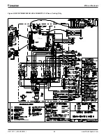
Page 46: ...OM 1077 1 MAVERICK I 46 www DaikinApplied com Wiring Diagrams Figure 23 MPS015B MPS025B 208 230 460 575V 3 Phase Cooling Only DDC Controller...

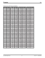
Page 47: ...359 32 0 32 654 105 8 5 117 181 4 1 140 255 2 349 33 8 31 030 107 6 4 918 183 2 1 104 257 0 340 35 6 29 498 109 4 4 727 185 0 1 070 258 8 332 37 4 28 052 111 2 4 544 186 8 1 037 260 6 323 39 2 26 686...

Page 48: ...nt to its standard terms and conditions of sale including Limited Product Warranty Consult your local Daikin Applied representative for warranty details To find your local Daikin Applied representativ...

Reviews: