www.DaikinApplied.com 65
IM 830-6
Unit Ventilator(s) Start-up
Remove debris, dust, dirt and any obstruction from the outside
air ducting, return air ducting (if applicable) and discharge air (if
applicable) as this will affect unit performance.
NOTICE
1. Open the bottom-hinged access panels.
Before proceeding, inspect the fan system to be sure that
all parts are aligned properly and move freely. Inspect
fans and fan discharge area for obstructions. Rotate
fans manually. Check that a clean filter is installed and
ductwork to and from the unit ventilator is free of debris.
2. All panels should be in place and properly fastened.
Do not attempt to operate the unit fans until the fan bearings have
been oiled. Oiled bearings provide smooth, and quiet operation of
the fan system.
CAUTION
!
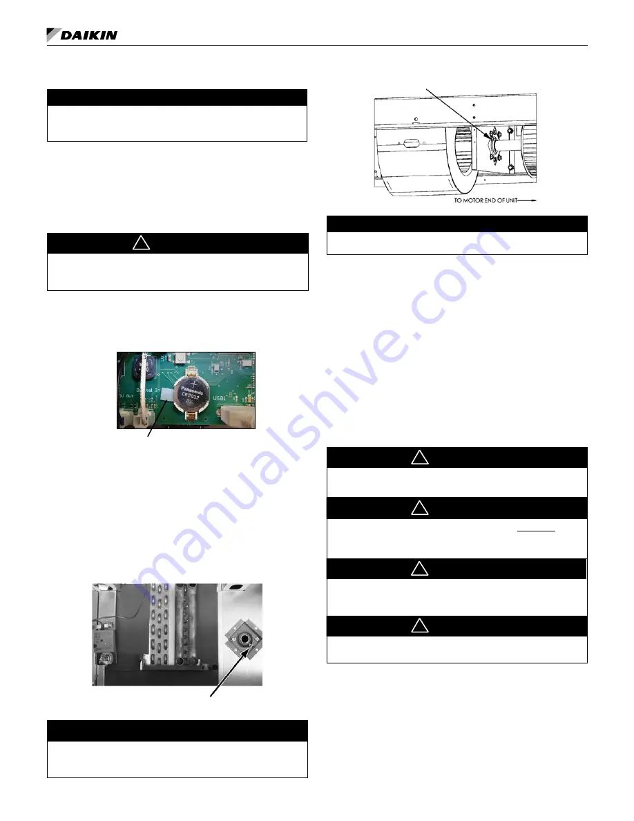
Remove Battery Shipping Tab
Check that board backup battery shipping tab is removed. To
remove, grasp tab and gently pull. Battery should be replaced
every 3 years of unit service.
Remove Battery ShippingTab
Oiling the Fan Shaft End Bearing
Access to fan shaft bearing is through bottom hinged access
panel, in the units left end compartment (
the oiler cap. Oil, using a few drops of high grade SAE 20 or
30 non detergent oil. Periodically oil the bearing every 6-12
months to maintain proper lubrication.
Figure 104: Oiling Point
Note:
Access to the Fan Shaft Bearing Through the Bottom, Large-
Hinged Access Panel. The bearing is located at the Left End
of the Unit.
Bearing Oiler Cap
For 1500 and 2000 cfm units, access to the fan shaft bearing is
through the bottom hinged access panel. It is located between
the third and fourth fan housing from the right (
).
NOTICE
Figure 105: Oiling Point for 1500 and 2000 cfm units
Bearing Oiler Cap
NOTICE
G.E. motor manufacturer recommends not oiling the fan motor.
Start-up Procedure
1. After the unit ventilator has been properly installed,
activate unit electrical power and applicable chilled water/
hot water/steam/refrigerant systems.
2. Using the applicable control, activate the unit ventilator.
Depending on the operating mode selected, the dampers,
fans, and other components should operate as needed.
3. Run the unit ventilator for ten minutes, listening and
observing. Fans should be operating correctly and rotating
in proper direction, without unusual noise. Likewise,
the unit should be free of sheet metal rattles and / or
unusual noises. All panels should be in place and properly
fastened. Check for air leaks and condensation.
Filter Access and Removal
With Daikin’s single-filter design, filter change out takes only
minutes.
Turn off unit before servicing to avoid danger of electric shock, and
injury from moving parts.
CAUTION
!
Units must have a filter installed when operating. Operation without
a filter can compromise unit performance due to build up of dust and
dirt on components.
Dirty or clogged filters can impact unit performance, resulting in
damage to the unit.
Electric heat units should ONLY use permanent wire mesh filters.
Filters other than wire mesh are not intended for electric heat units,
and can cause unit damage, property damage or personal injury.
CAUTION
!
CAUTION
!
CAUTION
!
Turn off the unit, (fan speed switch or unit on/off switch is
located behind the bottom access panel, located in the right
end compartment).
The AH Model filter is removed by fully opening the bottom,
louvered hinged access panel (
). Release the ends of the safety chains (2) attached
at the unit frame to allow full swing of the louvered panel (
). Loosen (do not remove) the two (2) hex head screws on the
slotted filter bracket, and slide the –filter bracket away to provide


