background image

IM 820

  Page 1

Installation and Maintenance Manual

IM-820

Group: 

Unitary

Part Number: 

IM-820

Date: 

March 2005

Supersedes: New

© 2005 

Daikin

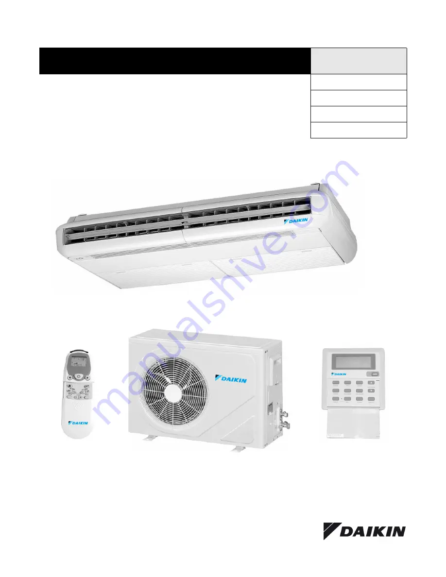
MCM Ceiling/Floor Convertible Split Type Air Conditioner

Outdoor Unit

Indoor Unit

Wireless Remote

Control (Standard)

Wired Wall

Control (Optional)

Summary of Contents for IM-820

Page 1: ...nance Manual IM 820 Group Unitary Part Number IM 820 Date March 2005 Supersedes New 2005 Daikin MCM Ceiling Floor Convertible Split Type Air Conditioner Outdoor Unit Indoor Unit Wireless Remote Control Standard Wired Wall Control Optional ...

Page 2: ...ecial Features 20 Dry mode 20 Heat mode heat pump only 20 Overheating protection heat pump only 20 Frost prevention 20 Fan speed and rated cooling capacity 20 Operating Conditions 20 Cooling 20 Overall Checking 20 Unit Indicator Lights 21 IR signal receiver 21 Netware 2 Wired Wall Control Optional 21 Service and Maintenance 22 Electrostatic Filters 22 Filter Replacement 22 Startup After Extended S...

Page 3: ...nect power before servicing can cause severe personal injury or death CAUTION Use copper conductors only Unit terminals are not designed to accept other types of conductors Failure to do so can cause damage to the equipment CAUTION Do not install in a laundry room Humidity and laundry chemicals can corrode unit components Do not install the unit where leakage of flammable gas may occur If gas leak...

Page 4: ... 3 4 47 3 4 47 3 4 67 1 2 67 1 2 D 26 1 2 26 1 2 26 1 2 26 1 2 26 1 2 E 6 1 4 6 1 4 6 1 4 6 1 4 6 1 4 F 2 1 4 2 1 4 3 3 4 3 3 4 3 3 4 G 20 1 2 20 1 2 20 1 2 20 1 2 20 1 2 H 22 22 22 22 22 E F B G D A C H Two mounting brackets shipped attached to the indoor unit See page 7 for more detail Model MLC 20 25 B BR 30 40 50C CR A 16 19 1 4 B 33 40 1 2 C 25 1 2 33 1 2 D 2 1 4 3 1 2 E 13 1 4 15 3 4 E D B A...

Page 5: ...bstruc tion on top Select the coolest possible place where intake air temperature is not greater than the outside air temperature maximum 113 F See Table 1 Page 7 for weight of outdoor unit Figure 1 Outdoor Unit Minimum Clearances Air Discharge Swing Baffle IR Receiver and LED Indicator Lights Air Discharge Grille Air Intake Grille Air Intake Air Discharge Nozzle Refrigerant Tubing and Insulation ...

Page 6: ...ient wiring and piping Indoor Unit Clearances The indoor unit must be installed in a manner to prevent mixing the cool discharged air with the hot return air Follow the instal lation clearances shown in Figure 2 Do not place the indoor unit in direct sunlight The location must be suitable for piping and drainage and be away from doors or windows Figure 2 Indoor Unit Minimum Clearances 12 min 19 68...

Page 7: ...nit Weight lbs Figure 3 Slope for condensate drainage Semi enclosed Mounting In case the unit is to be half recessed into a false ceiling make sure the unit is well aligned with the ceiling Provide the installation space as shown in Figure 4 Figure 4 Semi enclosed Mounting Model 20 25 30 40 50 Weight ID Unit 95 99 99 154 154 Weight OD Unit 125 128 209 220 231 1 8 Ceiling Mount Slope Wall Floor Mou...

Page 8: ... See Figure 6 Remove burrs from cut ends by holding tubing down wards to prevent metal chips from entering the tubing Slide the flare nuts for both the indoor unit and outdoor unit onto the copper tubing Flare the tubing as shown in Figure 6 and Table 3 The flare must be even and not cracked or scratched Figure 6 Cutting and Flaring Tube Table 3 Tube Flaring Dimensions Tubing Connection To Units C...

Page 9: ...ck on This will require two disconnects one by the outdoor unit and one by the indoor unit Table 5 Wire Fuse Breaker Requirements Cooling Only Table 6 Wire Fuse Breaker Requirements Heat Pump Only Not including the low voltage OD coil sensor cable WARNING Improper installation can cause severe personal injury or death Wiring must be done by a qualified technician in compliance with local codes Uni...

Page 10: ...LOW FH FM FL GREEN YELLOW COMP N NOTE DISCONNECT CN6 IF CN4 IS USED KEY FIELD SUPPLY WIRING AS AIR SWING MOTOR L N WHITE BLACK BLACK RED G Y L1 L2 208 230V 1 PHASE 60Hz FAN MOTOR COMPRESSOR C S R CAPACITOR CAPACITOR BROWN RED BLUE BLUE BLUE BLUE RED WHITE COMP N GREEN YELLOW BROWN RED WHITE BLACK GREEN YELLOW FAN MOTOR IC AC MC BLACK MODEL MCM20D 25D INDOOR UNIT COOLING ONLY MODEL MLC20B 25B OUTDO...

Page 11: ...KEY FIELD SUPPLIED WIRING AS AIR SWING MOTOR 208 230V 1 PH 60HZ L2 L1 10A REDRED BLUE REDRED RED R L1S L2 T L3 U T1V T2W T3 A2 A1 BLACK RED BLUE WHITE COMP L N GREEN YELLOW WHITE RED G Y FAN MOTOR BROWN BROWN C COMPRESSOR CRANKCASE HEATER NOTE FIELD INSTALL 10A FUSE IN BLUE AND RED WIRE AS SHOWN MODEL MCM 030D INDOOR UNIT COOLING ONLY MODEL MLC30C OUTDOOR UNIT S R L N BLUE 10A RED G Y HIGH LOW PRE...

Page 12: ... AIR SWING MOTOR 208 230V 1 PH 60Hz L2 L1 10A FUSE RED RED REDRED RED RED RED RED REDRED RED 1L1 3L2 5L3 2T1 4T2 6T3 1 2 A2 A1 BLUE BLACK BLUE BLUE RED BLACK BLACK BLUE BLUE GREEN YELLOW PURPLE PURPLE WHITE COMP L L1 N L2 GREEN YELLOW RED BLUE WHITE RED G Y FAN MOTOR BROWN BROWN C R S COMPRESSOR BLUE CRANKCASE HEATER LOW PRESSURE SWITCH HIGH PRESSURE SWITCH LOCK OUT RELAY 2 10A FUSE MODEL MCM40D 5...

Page 13: ... USED KEY FIELD SUPPLIED WIRING AS AIR SWING MOTOR 4WV 4 WAY VALVE WHITE FAN MOTOR MODEL MCM20DR 25DR INDOOR UNIT HEAT PUMP MOEL MLC20BR 25BR OUTDOOR UNIT L N WHITE BLACK BLACK RED G Y GREEN YELLOW KEY FIELD SUPPLIED WIRING 4V 4 WAY VALVE TH2 OUTDOOR THERMISTOR AS AIR SWING MOTOR OF 4WV BLUE BROWN COMP N OF 4WV BLUE BLUE BLACK GREEN YELLOW RED RED WHITE BLACK 4V BLACK BLACK BROWN BROWN BLACK BLUE ...

Page 14: ...UE COMP L N RED BLUE C R S COMPRESSOR NOTE FIELD INSTALL 10A FUSE IN BLUE AND RED WIRE AS SHOWN MODEL MCM 30DR INDOOR UNIT HEAT PUMP MODEL MLC30CR OUTDOOR UNIT A 4WV L N BLUE 10A FUSE RED G Y HIGH PRESSURE SWITCH RED RED TO OUTDOOR DEFROST SENSOR OF GREEN YELLOW COMP OF 4WV A BLUE BLACK BROWN BLACK L1 T1 BLUE WHITE WHITE CRANKCASE HEATER GREEN YELLOW WHITE BLUE BROWN BROWN FAN MOTOR WHITE BLACK BL...

Page 15: ... 1L1 5L3 1 2T1 6T3 2 A2 A1 BLUE COMP L N RED BLUE C R S COMPRESSOR NOTE FIELD INSTALL 10A FUSE IN BLUE AND RED WIRE AS SHOWN MODEL MCM 40DR 50DR INDOOR UNIT MODEL MLC40CR 50CR A 4WV L N BLUE 10A FUSE RED G Y HIGH PRESSURE SWITCH RED RED TO OUTDOOR DEFROST SENSOR OF GREEN YELLOW COMP L1 L2 OF 4WV A BLUE BLACK BROWN BLACK 3L2 4T2 BLUE WHITE WHITE CRANKCASE HEATER GREEN YELLOW PURPLE BLUE BLUE BROWN ...

Page 16: ...IT COOLING ONLY OPTIONAL LOW AMBIENT KIT 208 230V 1 PHASE 60HZ OL MODEL MLC 20BR 25BR OUTDOOR UNIT HEAT PUMP OPTIONAL LOW AMBIENT KIT 208 230V 1 PHASE 60HZ FM CM 4 3 2 1 FSCM COMP E N OF 4V TO INDOOR UNIT RED BLACK TH2 BLACK 4V BLACK BLACK ORANGE BLACK YELLOW BROWN BROWN BROWN BLUE BLACK WHITE BLUE BLUE WHITE BLACK BLUE GREEN YEL RED BLUE C S R KEY FM FAN MOTOR CM COMPRESSOR MOTOR 4V 4 WAY VALVE T...

Page 17: ...ing when tubing length is more than 25 ft and maximum tubing length Charge operation This operation must be done by weighing the R 22 being added thru the service port on the 3 way suction valve See Table 7 and Figure 10 1 Remove the service port cap 2 Connect the low pressure side of the charging gauge to the suction service port center of the cylinder tank and close the high pressure side of the...

Page 18: ...ature Setting Set the desired room temperature by pressing the buttons to increase or decrease the set temperature The temperature setting range is from 60 F to 86 F Press both buttons simultaneously to toggle the temperature setting between C and F Automatic Air Swing Press the SWING button to activate the automatic air swing function To distribute the air to a specific direction press the SWING ...

Page 19: ...baffle for better air dis tribution 9 Display normally shows room temperature Momen tarily shows set point when a change is made 10 Heat symbol blinks while outdoor coil defrosts heat pump only 11 Error codes blink on display E1 Room sensor loose or defective E2 Indoor coil sensor loose or defective E3 Outdoor coil sensor loose or defective E4 Compressor cycling on overload E5 Low refrigerant char...

Page 20: ...speed Operating Conditions Cooling 32 F on size 20 and 25 23 F on size 30 40 and 50 with optional Low Ambient Kit Heating heat pump only Ts Dry Bulb Temperature Th Wet Bulb Temperature Overall Checking Ensure that 1 The unit has been mounted properly 2 Refrigerant tubing connections have been checked for leaks 3 Proper wiring and circuit breakers have been installed Drainage check Check condensate...

Page 21: ...ows E1 Room sensor loose or defective E2 Indoor coil sensor loose or defective E3 Outdoor coil sensor loose or defective E4 Compressor cycling on overload E5 Low refrigerant charge Optional Wired Wall Control Air Filters Air Intake Grille Air Discharge Grille IR Receiver and LED Indicator Lights Air Discharge Swing Baffle Wireless Remote Control INDOOR UNIT Cool Dry Fan Cool Dry Fan Heat Cooling U...

Page 22: ...hooting If any malfunction of the unit is noted immediately switch off the power supply Check the following chart for possible causes treatments If the trouble persists please call your local dealer service man WARNING Disconnect the electrical power supply before performing any service maintenance or troubleshooting WARNING Disconnect the main power supply before opening the return air grille DO ...

Page 23: ...anel by wiping it using soft cloth soaked in lukewarm water below 40 C 104 F with neutral detergent solution Note Do not use gasoline volatile substances or chemicals to clean the unit Every year Condense Drain Pan and Pipe Check and clean if necessary Every year Indoor Fan Check for abnormal noise Every year Indoor Outdoor Coil Clean the louvers and coil Be careful not to bend or flatten the alum...

Page 24: ...in This document contains the most current product information as of this printing For the most up to date product information please go to www DaikinApplied com Daikin Applied 800 432 1342 www DaikinApplied com ...

Reviews: