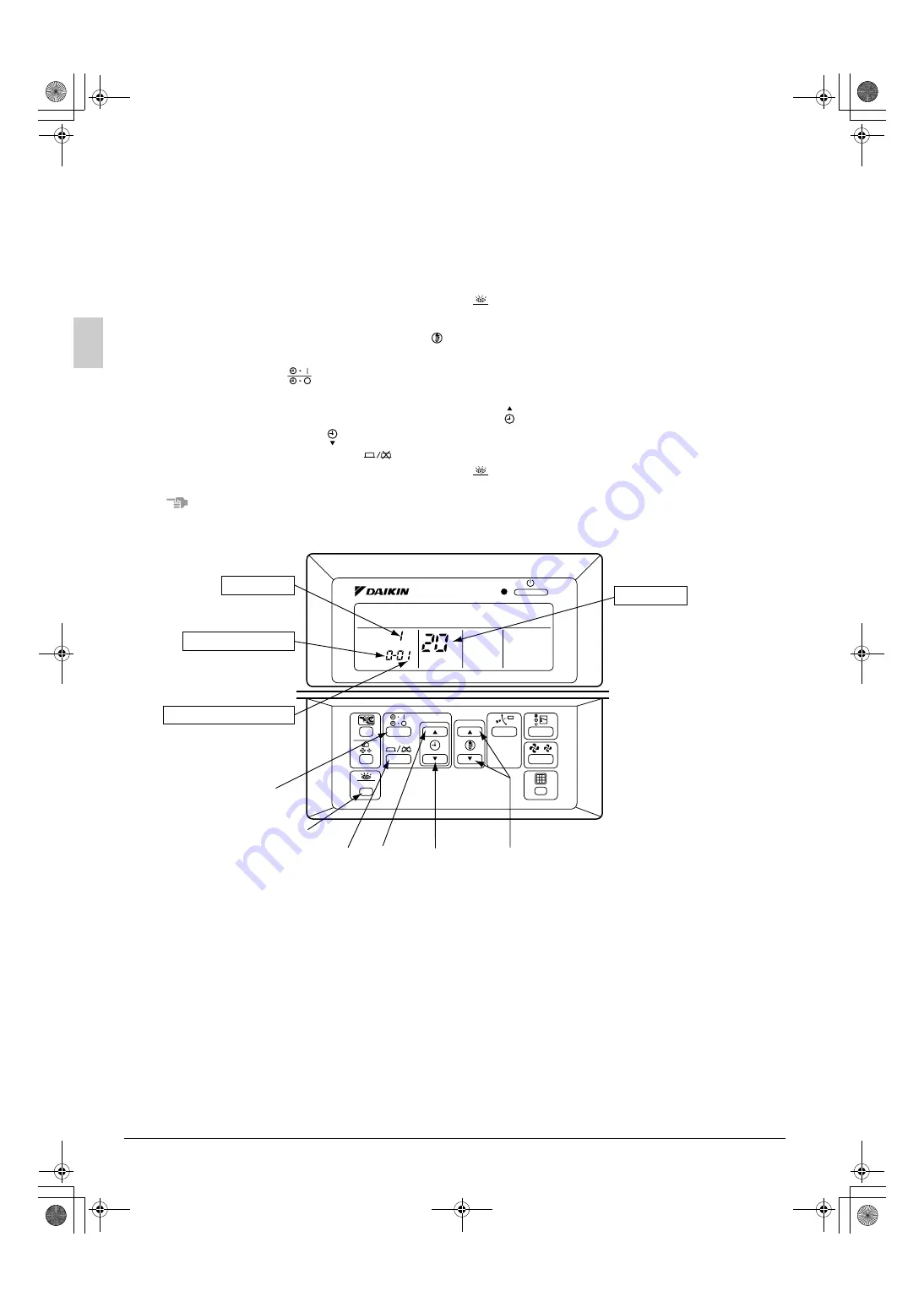
background image

16

English

11. FIELD SETTING

Field setting


Field setting must be made from the remote controller in accordance with the installation conditions. 

• Setting can be made by changing the “Mode No.”, “FIRST CODE NO.”, and “SECOND CODE NO.”.
• Refer to the following procedure for Field setting.

〈 

Procedure 

(1) Press the INSPECTION/TEST OPERATION button ( 

 ) for 4 seconds or more in normal mode to 

change to “FIELD SETTING MODE”.

(2) Press the TEMPERATURE SETTING button (   ) and choose the desired “Mode No.”.
(3) Under group control, if setting on each indoor unit is to be performed, press the TIMER MODE 

START/STOP button ( 

 ) and select the indoor unit number. 

(Unnecessary in case of unified setting of group control)

(4) Press the PROGRAMING TIME upper part of the button ( 

 ) and select the “FIRST CODE NO.”.

(5) Press the part of the button (   ) and select the “SECOND CODE NO.”.

(6) Press the TIMER ON/OFF button ( 

 ) once to fix the change of the setting.

(7) Press the INSPECTION/TEST OPERATION button ( 

 ) to return to the “NORMAL MODE”.

NOTE

Setting is performed by a group as a seto when individual setting of each indoor unit is required, or when 
the setting results must be checked, use the mode number is (    ).

1. Setting air filter sign

Control panels are equiped with the liquid crystal display of air filter signs to display the time to clean 
air filters.

Change the “ SECOND CODE NO.” according to Table 2 depending on the amount of dirt or dust in the 
room.
(“SECOND CODE NO.” is factory set to “01” for filter contamination-light)

TEST

TEST

SETTING

TEST

UNIT NO.

Mode No.

SECOND CODE NO.

FIRST CODE NO.

UNIT NO.

(4)

(5)

(2)

(3)

(6)

(1)(7)

01_EN_3PA60136-8Y.fm  Page 16  Saturday, December 22, 2007  1:04 PM

Summary of Contents for FVQ100BV1B

Page 1: ...RA LEER EN CASO DE TENER ALGUNA DUDA PRIMA DELL INSTALLAZIONE LEGGERE ATTENTAMENTE QUESTE ISTRUZIONI TENERE QUESTO MANUALE A PORTATA DI MANO PER RIFERIMENTI FUTURI LEES DEZE INSTRUCTIES ZORGVULDIG DOO...

Page 2: ...FHY100BJV1 FHY125BJV1 FH35BJV1 FH45BJV1 FH60BJV1 II FHYP35BV1 FHYP45BV1 FHYP60BV1 FHYP71BV1 FHYP100BV1 FHYP125BV1 FH35BZV1 FH45BZV1 FH60BZV1 III FHQ35BUV1B FHQ50BUV1B FHQ60BUV1B FHQ71BUV1B FHQ100BUV1...

Page 3: ...rty damage or personal injury which may be serious depending on the circumstances WARNING Ask your dealer or qualified personnel to carry out installation work Do not attempt to install the air condit...

Page 4: ...e breaker may result in electric shocks or fire CAUTION While following the instructions in this installation manual install drain piping to ensure proper drainage and insulate piping to prevent conde...

Page 5: ...ETTING install them on an adequate place referring to the related technical information As for the installation procedure follow the instruction in Remote controller installation procedure attached to...

Page 6: ...e The unit may malfunction or the components burn out Are wiring and piping correct The unit may malfunction or the components burn out Is the unit safely grounded Dangerous at electric leakage Is wir...

Page 7: ...nit power supply wiring and transmission wiring at least 1 meter away from televisions and radio receivers This is to prevent image interference and noise in those electrical appliances Noise may be g...

Page 8: ...ompletely on both sides of the gas piping and the liquid piping Otherwise a water leakage can result sometimes When using a heat pump the temperature of the gas piping can reach up to approximately 12...

Page 9: ...ut included with the unit main body CAUTION Do not let oil get on the screw holders on the dressing board Oil can weaken the screw holders Table 1 Refer to Table 1 to determine the proper tightening t...

Page 10: ...g through the hole on the bottom frame After rigging pipes and wiring lock down the refrigerant pipes drain hose inside the unit indoor outdoor unit transmission wiring and grounding line in the pipin...

Page 11: ...smoothly and that water does not leak from connections Carefully pour approximately 1 000cc of water through the air discharge outlet so that it falls directly onto the heat exchanger at an angle with...

Page 12: ...troller cable from the remote controller terminal board 2 Remove the remote controller holding plate on the back side of the front plate panel 3 Fix the attached hole covering plate on the front plate...

Page 13: ...r with screw drivers etc 2 Attach the remote controller wiring 3 Reassemble the remote controller in the opposite order of 1 and at last install the attached remote controller lid 7 6 After the remote...

Page 14: ...angerously high if hit by lightning Specifications for field wire NOTE 1 Shows only in case of protected pipes Use H07RN F in case of no protection 2 Insulated thickness 1mm or more Methods of wiring...

Page 15: ...the screw may be damaged The tightening torque of each terminal screw is shown in the table on the right hand side 9 WIRING EXAMPLE For the wiring of outdoor units refer to the installation manual att...

Page 16: ...oller must be set to MAIN and the other to SUB MAIN SUB CHANGEOVER 1 Insert a screwdriver into the recess between the upper and lower part of remote controller and working from the 2 positions pry off...

Page 17: ...it the grille stopper front panel into the groove on the air intake grille and lock the grille down in its original place by screw See below figure Be careful not to overtighten screws S M M S Factory...

Page 18: ...upper part of the button and select the FIRST CODE NO 5 Press the part of the button and select the SECOND CODE NO 6 Press the TIMER ON OFF button once to fix the change of the setting 7 Press the INS...

Page 19: ...N button 4 times 2 times for wireless remote controller and operate at Test Operation mode for 3 minutes 6 Push AIR FLOW DIRECTION ADJUST button to make sure the unit is in operation 7 Press INSPECTIO...

Page 20: ...igure of the error code flashes 6 Continue pressing the PROGRAMMING TIME button unit it makes a long beep and find the lower code A long beep indicate the error code NOTE 1 Press the INSPECTION TEST O...

Page 21: ...c thermal outdoor unit Possible electrical overload in the compressor or cut line in the compressor motor L9 Stall prevention outdoor unit Compressor possibly locked LC Transmission malfunction betwee...

Page 22: ...emote controller UA Miss setting for multi system Error in multi system settings for simultaneous ON OFF operation UC Central control address overlapping UJ Transmission failure in accessory equipment...

Page 23: ...ASE OF PROTECTED PIPES USE H07RN F IN CASE OF NO PROTECTION INDOOR UNIT A1P PRINTED CIRCUIT BOARD CAPACITOR SIGNAL RECEIVER CIRCUIT CONNECTOR FOR OPTIONAL PARTS THERMISTOR AIR THERMISTOR COIL MAGNETIC...

Page 24: ...0802 HT 3PA60136 8Y EM07A043A 00_CV_3PA60136 8Y fm Page 2 Saturday December 22 2007 1 03 PM...

Reviews: