background image

English

1-13

SPECIAL PRECAUTIONS WHEN DEALING WITH R410A UNIT

R410A is a new HFC refrigerant which does not damage the 
ozone layer. The working pressure of this new refrigerant is 
1.6 times higher than conventional refrigerant (R22), thus 
proper installation/servicing is essential.

Never use refrigerant other than R410A in an air conditioner 
which is designed to operate with R410A.
POE or PVE oil is used as lubricant for R410A compressor, 
which is different from the mineral oil used for R22 
compressor. During installation or servicing, extra precaution 
must be taken not to expose the R410A system too long 
to moist air. Residual POE or PVE oil in the piping and 
components can absorb moisture from the air.
To prevent mischarging, the diameter of the service port 
on the flare valve is different from that of R22.

Use tools and materials exclusively for refrigerant R410A. 
Tools exclusively for R410A are manifold valve, charging 
hose, pressure gauge, gas leak detector, flare tools, torque 
wrench, vacuum pump and refrigerant cylinder.
As an R410A air conditioner incurs higher pressure 
than R22 units, it is essential to choose the copper pipes 
correctly. Never use copper pipes thinner than 0.8mm even 
though they are available in the market. 
If the refrigerant gas leakage occurs during installation/
servicing, be sure to ventilate fully. If the refrigerant gas 
comes into contact with fire, a poisonous gas may occur.
When installing or removing an air conditioner, do not 
allow air or moisture to remain in the refrigerant cycle.

VACUUMING AND CHARGING

Vacuuming is necessary to eliminate all moisture and air from the system. 

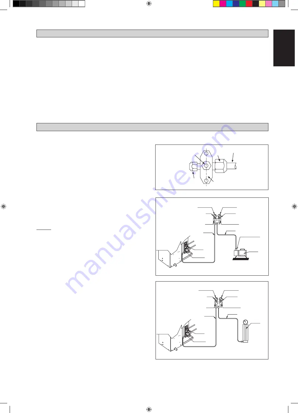
Vacuuming The Piping And The Indoor Unit

Except for the outdoor unit which is pre-charged with 
refrigerant, the indoor unit and the refrigerant connection 
pipes must be air-purged because the air containing moisture 
that remains in the refrigerant cycle may cause malfunction 
of the compressor.

Remove the caps from the valve and the service port.
Connect the center of the charging gauge to the vacuum 
pump.
Connect the charging gauge to the service port of the 3-way 
valve.
Start the vacuum pump. Evacuate for approximately 30 
minutes. The evacuation time varies with different vacuum 
pump capacity. Confirm that the charging gauge needle has 
moved towards -760mmHg.

Caution

If the gauge needle does not move to -760mmHg, be sure to 
check for gas leaks (using the refrigerant detector) at flare 
type connection of the indoor and outdoor unit and repair 
the leak before proceeding to the next step.
Close the valve of the changing gauge and stop the vacuum 
pump.
On the outdoor unit, open the suction valve (3 way) and 
liquid valve (2 way) (in anti-clockwise direction) with 4mm 
key for hexagon sacked screw.

Charge Operation

This operation must be done by using a gas cylinder and a 
precise weighing machine. The additional charge is topped-up 
into the outdoor unit using the suction valve via the service 
port.

Remove the service port cap.
Connect the low pressure side of the charging gauge to the 
suction service port center of the cylinder tank and close 
the high pressure side of the gauge. Purge the air from the 
service hose.
Start the air conditioner unit.
Open the gas cylinder and low pressure charging valve.
When the required refrigerant quantity is pumped into 
the unit, close the low pressure side and the gas cylinder 
valve.
Disconnect the service hose from service port. Put back 
the service port cap.


Refrigerant Piping

Outdoor Unit 3 ways valve

Allen key

Service Port

Flare nut

HIGH PRESSURE GAUGE

GAUGE MANIFOLD

LOW PRESSURE GAUGE

HANDLE 

HI 

(ALWAYS CLOSED)

CHARGE HOSE

-760mmHg

HANDLE 

LO

CHARGE HOSE

VACUUM PUMP 
ADAPTER FOR 
COUNTER FLOW 
PREVENTION

CHECK VALVE

LIQUID VALVE

HIGH PRESSURE GAUGE

LOW PRESSURE GAUGE

GAUGE MANIFOLD

-760mmHg

HANDLE 

LO

HANDLE 

HI 

(ALWAYS CLOSED)

CHARGE HOSE

CHARGE HOSE

CHECK VALVE

LIQUID VALVE

GAS VALVE 
(3-WAY)

CONFIGURATION OF AIR 
PURGE BY CHARGING

GAS VALVE 
(3-WAY)

CONFIGURATION OF AIR 
PURGE BY CHARGING

1 IM-5WMYJ-1113(2)DK_EN-39396B.i13   13

1 IM-5WMYJ-1113(2)DK_EN-39396B.i13   13

4/23/14   12:02:16 PM

4/23/14   12:02:16 PM

Summary of Contents for FTXN25MV1B

Page 1: ...FTK35JXV1 RK35FXV1 FTK50JXV1 RK50CXV1 FTK60JXV1 RK60CXV1 Installation Manual R410A Split Series Manuale d installazione Serie Multiambienti R410A Installationsanleitung Split Baureihe R410A Manual de...

Page 2: ...CVR IM 5WMYJ 1113 2 DK EN 39396B2 2 CVR IM 5WMYJ 1113 2 DK EN 39396B2 2 4 23 14 12 07 15 PM 4 23 14 12 07 15 PM...

Page 3: ...R INSIDE NAME PLATE TERMINAL BLOCK WITH EARTH TERMINAL F E J G G L D B K M A Gas pipe end INSTALLATION PLATE 25 35 Liquid pipe end Through the wall hole 65mm All dimensions are in mm Drain hose positi...

Page 4: ...mm Drain hose position Liquid pipe end Gas pipe end INSTALLATION PLATE 50 60 Recommended mounting plate retention spots 7 spots in all All dimensions are in mm Recommended mounting plate retention spo...

Page 5: ...XN RK All dimensions are in mm Dimension Model A B C D E F G H I J K L M N 50 60 855 730 328 520 179 46 93 149 101 113 603 126 164 15 All dimensions are in mm Dimension Model O P Q R S T U V 50 60 34...

Page 6: ...melt or deform as a result of excessive heat or chemical reaction When the unit is used in kitchen keep flouraway from going into suction of the unit This unit is not suitable for factory used where...

Page 7: ...the inside of the service cover factory refrigerant charge of the product see unit name plate 2 additional refrigerant amount charged in the field total refrigerant charge contains fluorinated greenho...

Page 8: ...ove the service lid screws 2 Pull out the service lid diagonally down in the direction of the arrow 3 Pull down 500mm from wall Where a wall or other obstacle is in the path of outdoor unit s intake o...

Page 9: ...the upper part of the unit please allow more space than the figure indicated in the above table Dimension A B C D Minimum Distance mm 300 1000 300 500 Condensed Water Disposal Of Outdoor Unit Heat Pum...

Page 10: ...the side and bottom out hold the bottom of the piping and then position it to the required direction The condensation drain hose can be taped to the pipes Right side right back or right bottom piping...

Page 11: ...25 35 FTK 25 35 When stripping the ends of interconnecting wires in advance bind right ends of wires with insulating tape Hand indoor unit s hook here Mounting plate Interconnecting wires Wire guide...

Page 12: ...IGERANT PIPING Additional Charge The refrigerant is pre charged in the outdoor unit If the piping length is less than 7 5m then additional charge after vacuuming is not necessary If the piping length...

Page 13: ...pes The exact length of pipe protruding from the top surface of the swaging block is determined by the flaring tool See Figure III Fix the pipe firmly on the swaging block Match the centers of both th...

Page 14: ...terminal connectors and wires Make sure all the covers are properly fixed to avoid any gap Use round crimp style terminal for connecting wires to the power supply terminal block Connect the wires by...

Page 15: ...from the valve and the service port Connect the center of the charging gauge to the vacuum pump Connect the charging gauge to the service port of the 3 way valve Start the vacuum pump Evacuate for app...

Page 16: ...ows the LED indicator lights for the air conditioner unit under normal operation and fault conditions The LED indicator lights are located at the side of the air conditioner unit The heat pump units a...

Page 17: ...EMP CWB Heat Pump Model INDOOR TEMP CDB OPERATING RANGE DB Dry bulb WB Wet bulb DB Dry bulb WB Wet bulb Model FTXN 25 35 RXN 25 35 20 15 0 3 7 2 5 2 0 1 20 18 10 0 10 15 20 50 46 43 40 30 20 10 10 14...

Page 18: ...hildren If you keep this Bio Filter for a long time please keep it unopened and store in a cool place avoiding direct sunlight Please dispose the old Bio Filter as nonflammable garbage after use Opera...

Page 19: ...Remove any dust adhering to the filter by using a vacuum cleaner or wash in lukewarm water below 40 C 104 F with a neutral cleaning detergent Rinse the filter well and dry before placing it back onto...

Page 20: ...h might have adhered onto the coil Condensation on the front air grille of the indoor unit 5 This is caused by air humidity after an extended long period of operation The set temperature is too low in...

Page 21: ...de este manual y en su traducci n a cualquier idioma prevalecer la versi n inglesa El fabricante se reserva el derecho a modificar cualquiera de las especificaciones y dise os contenidos en el present...

Reviews: