background image

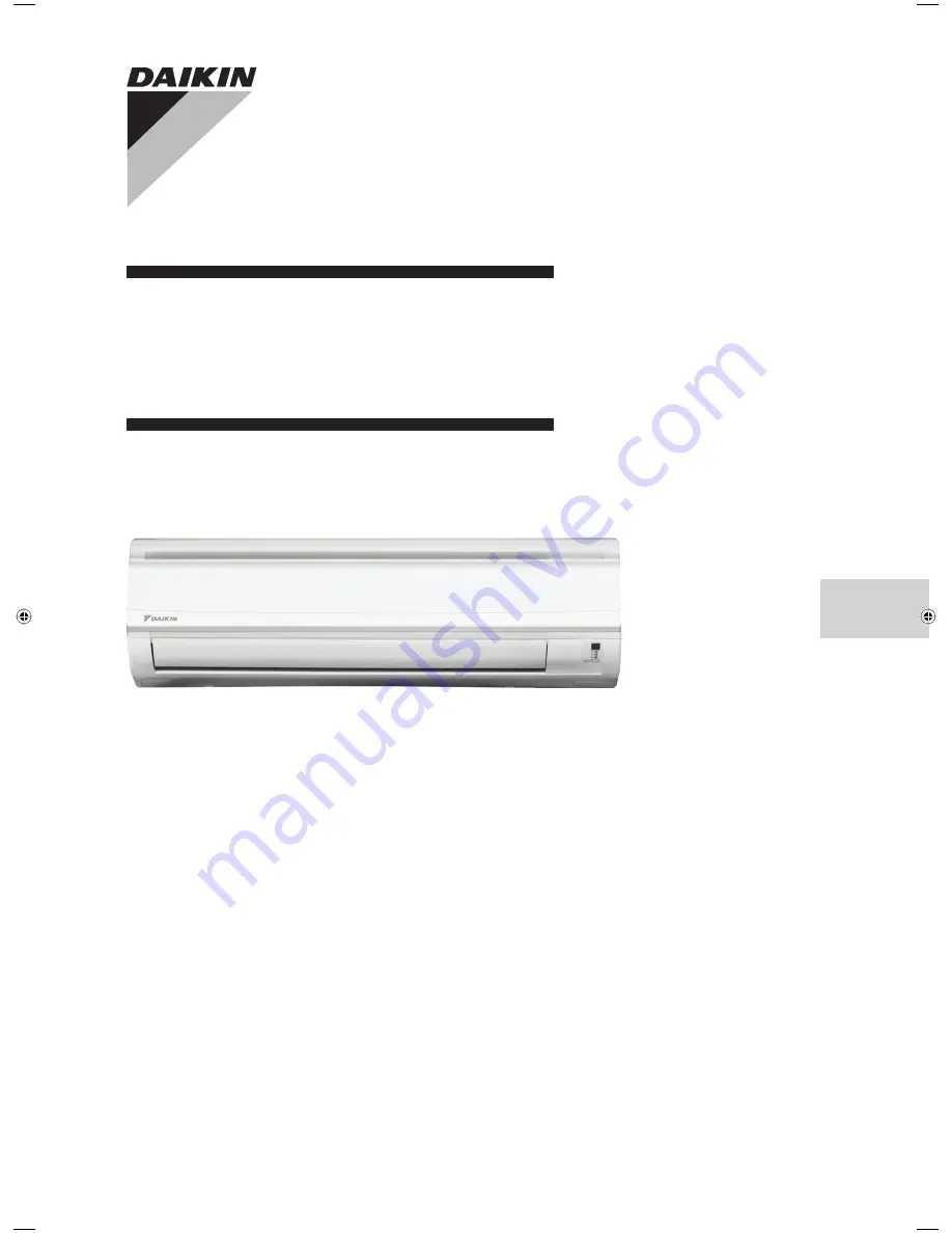
INSTALLATION
MANUAL

MODELS
FTS20JEV1K   RS20JEV1K
FTS25JEV1K

RS25JEV1K

R410A SPLIT SERIES

English

Installation Manual

R410A Split Series

IM-5WMJ-0811(0)-DAIKIN

Part No.: R08019036975

1-CVR EN-IM 5WMJ-0811(0)Daikin.i1   1

1-CVR EN-IM 5WMJ-0811(0)Daikin.i1   1

10/18/11   1:50:43 PM

10/18/11   1:50:43 PM

Summary of Contents for FTS20JEV1K

Page 1: ...INSTALLATION MANUAL MODELS FTS20JEV1K RS20JEV1K FTS25JEV1K RS25JEV1K R410A SPLIT SERIES English Installation Manual R410A Split Series IM 5WMJ 0811 0 DAIKIN Part No R08019036975 ...

Page 2: ......

Page 3: ...E TERMINAL BLOCK WITH EARTH TERMINAL All dimensions are in mm Original Instruction OUTLINE AND DIMENSIONS Recommended mounting plate retention spots 7 spots in all D B G H J L M A K F I G F E Through the wall hole Ø 65mm Drain hose position Liquid pipe end Gas pipe end INSTALLATION PLATE FTS20 25JEV1K All dimensions are in mm Dimension Model A B C D E F G H I J K L M FTS20 25JEV1K 1065 310 228 190...

Page 4: ...n mm Outdoor Unit Dimension Model A B C D E F G H I J K L M N O RS20JEV1K 855 628 328 508 181 44 93 149 101 113 603 126 164 17 49 RS25JEV1K 855 730 328 520 182 44 93 149 101 113 603 126 164 17 34 Dimension Model P Q R S T RS20JEV1K 32 3 23 73 75 RS25JEV1K 32 3 23 73 75 ...

Page 5: ...ruseinroomwheremineraloil oilvapour or oil steam exist this may cause plastic part to melt or deform as a result of excessive heat or chemical reaction When the unit is used in kitchen keep flour away from going into suction of the unit Thisunitisnotsuitableforfactoryusedwherecuttingoil mist or iron powder exist or voltage fluctuates greatly Do not install the units at area like hot spring or oil ...

Page 6: ...ruction to the smooth air flow Please follow the installation clearances shown in the figure Select the coolest possible place where intake air temperature is not greater than the outside air temperature please refer operating range Installation clearances Obstacle Return air Service access Note If there is any obstacle higher than 2m or if there is any obstruction at the upper part of the unit pl...

Page 7: ... to the required position in order to align it with the holes For the side and bottom hold the bottom of the piping and then position it to the required direction see figure The condensation drain hose can be taped to the pipes Right side right back or right bottom piping min 50 Space for maintenance min 30 Space for performance Required space Right back piping Bind coolant pipe and drain hose tog...

Page 8: ...ation plate Engage the two hooks at the rear top of the indoor unit with the upper edge of the installation plate Ensure that the hooks are properly seated on the installation plate by moving it to the left and right How To Attach The Indoor Unit Hook the claws of the bottom frame to the mounting plate How To Remove The Indoor Unit Push up the marked area at the lower part of the front grille to r...

Page 9: ...e Size mm in 6 35 1 4 L E Remark The refrigerant pre charged in the outdoor unit is for piping length up to 7 5m Be sure to add the proper amount of additional refrigerant Failure to do so may result in reduced performance Additional refrigerant charge g per additional 1m length as tabulated Additional Charge The refrigerant is pre charged in the outdoor unit If the piping length is less than 7 5m...

Page 10: ...ll cause gas leak Insert the flare nuts mounted on the connection parts of both the indoor unit and outdoor unit into the copper pipes The exact length of pipe protruding from the top surface of the swaging block is determined by the flaring tool See Figure C Fix the pipe firmly on the swaging block Match the centers of both the swaging block and the flaring punch then tighten the flaring punch fu...

Page 11: ...be firmly connected All wires must not touch the refrigerant piping compressor or any moving parts of the fan motor The connecting wires between the indoor unit and the outdoor unit must be clamped on the wire clamps The power supply cord must be equivalent to H07RN F which is the minimum requirement Make sure no external pressure is applied to the terminal connectors and wires Make sure all the c...

Page 12: ...fire a poisonous gas may occur When installing or removing an air conditioner do not allow air or moisture to remain in the refrigerant cycle VACUUMING AND CHARGING Vacuuming is necessary to eliminate all moisture and air from the system The series II Outdoor Unit is provided with flare valve fittings Vacuuming The Piping And The Indoor Unit Except for the outdoor unit which is pre charged with re...

Page 13: ... Indicator Lights for Cooling Unit IR Receiver Cooling Unit The table shows the LED indicator lights for the air conditioner unit under normal operation and fault conditions The LED indicator lights are located at the right bottom of the air conditioner unit ON OFF Cool Timer Sleep ON OFF switch IR Receiver INDICATOR LIGHTS ON to OFF 1 Long Beep OFF to ON Pump down Cool force on 2 Short Beep Other...

Page 14: ...an mode on Dry mode on 1 time Room air sensor contact Loose Short Call your dealer Blink E1 3 times Outdoor coil sensor open Call your dealer Blink E3 2 times Indoor coil sensor open Call your dealer Blink E2 1 time Compressor overload Indoor coil sensor short outdoor coil sensor short Call your dealer Blink E4 Red Defrost operation 3 times Gas leak Call your dealer Blink E5 6 times Hardware error...

Page 15: ...ur on the louver thus resulting in drippings Frost Prevention When the air filter is dirty the evaporating temperature will decrease and eventually cause frosting If the evaporating temperature reaches 1 C 33 8 F the unit will trip Fan Speed And Rated Cooling Capacity The rated cooling capacity is provided at the HIGH fan speed The cooling capacity is lower when the unit is operating at MEDIUM and...

Page 16: ...e old Bio Filter as nonflammable garbage after use Operation with dirty filters 1 cannot deodorize the air 3 results in poor heating or cooling 2 cannot clean the air 4 may cause odour To order Bio Filter contact the service shop where you bought the air conditioner Open the front panel Hold the panel at the recesses on the main unit 2 recesses on right and left sides and lift it until it stops 1 ...

Page 17: ...left and pull it to the front side to remove it 2 Attach the front panel Align the right and left rotating shafts of the front panel with the grooves and push them all the way in Gently close the front panel Push both ends and the center on the front panel 3 Service Parts Maintenance Procedures Indoor air filter Remove any dust adhering to the filter by using a vacuum cleaner or wash in lukewarm w...

Page 18: ...ifications please contact the air conditioner unit installer The air flow is too low 3 The air filter is dirty The doors or windows are open The air suction and discharge are clogged The regulated temperature is not high enough Discharge air flow has bad odour 4 Odours may be caused by cigarettes smoke particles perfume etc which might have adhered onto the coil Condensation on the front air grill...

Page 19: ......

Page 20: ...ion of this manual shall prevail The manufacturer reserves the right to revise any of the specification and design contain herein at any time without prior notification Lot 60334 Persiaran Bukit Rahman Putra 3 Taman Perindustrian Bukit Rahman Putra 47000 Sungai Buloh Selangor Darul Ehsan Malaysia Zandvoordestraat 300 B 8400 Oostende Belgium ...

Reviews: