Printed Circuit Board Connector Wiring Diagram and Name
SIE-86
4
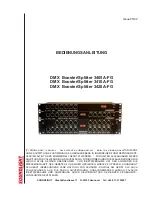
Printed Circuit Board Connector Wiring Diagram
1. Printed Circuit Board Connector Wiring Diagram and
Name
1.1
FTK25/35J Series, FTX25/35J Series
Printed circuit board (1) (Control PCB)
Printed circuit board (2) (Signal Receiver PCB)
Printed circuit board (3) (Intelligent Eye Sensor PCB)
Name of connector
Note:
Other designations
Control PCB (1)
1) S1
Connector for fan motor
2) S6
Connector for swing motor (Horizontal Flap)
3) S7
Connector for fan motor
4) S21
Connector for centralized control to 5 rooms
5) S27, S36
Connector for control PCB
6) S26
Connector for signal receiver PCB
7) S32
Connector for room temp/Heat exchanger thermistor
8) S35
Connector for Intelligent Eye Sensor PCB
1) V1
Varistor
2) JA
ADDRESS SETTING JAMPER
JB
Fan speed setting when compressor is OFF on thermostat.
JC
Power failure recovery function.
∗
Refer to page 121 for more detail.
3) SW7
OPERATION SWITCH
4) LED1 (GRN)
LED for operation
5) LED2 (YLW)
LED for timer
6) LED3 (GRN)
LED for intelligent eye
(RL001)
Control P C B (1)
S1
Signal receive P C B (2)
S27
GRN
GRN
YLW
LED1
LED2 LED3
SW7
S7
S6
Intelligent eye
sensor P C B (3)
S36
S35
S26
S32
S21
5V check
Jamper
JA
JB
JC
ground
12V check
Jamper
Si-86.book Page 4 Friday, June 23, 2000 10:26 AM