background image

English

13

CAUTION

CAUTION TO BE TAKEN WHEN BRAZING REFRIGERANT PIPING

“Do not use flux when brazing refrigerant piping. Therefore, use the phosphor copper brazing filler metal 
(BCuP-2/B-Cu93P-710/795) which does not require flux.”
(Flux has extremely harmful influence on refrigerant piping systems. For instance, if the chlorine based flux is 
used, it will cause pipe corrosion or, in particular, if the flux contains fluorine, it will damage the refrigerant oil.)

Before brazing field refrigerant piping, nitrogen gas shall be blown through the piping to expel air from the 
piping.
If you brazing is done without nitrogen gas blowing, a large amount of oxide film develops inside the piping, 
and could cause system malfunction.

When brazing the refrigerant piping, only begin brazing after having carried out nitrogen substitution or 
while inserting nitrogen into the refrigerant piping. Once this is done, connect the indoor unit with a flared 
or a flanged connection.

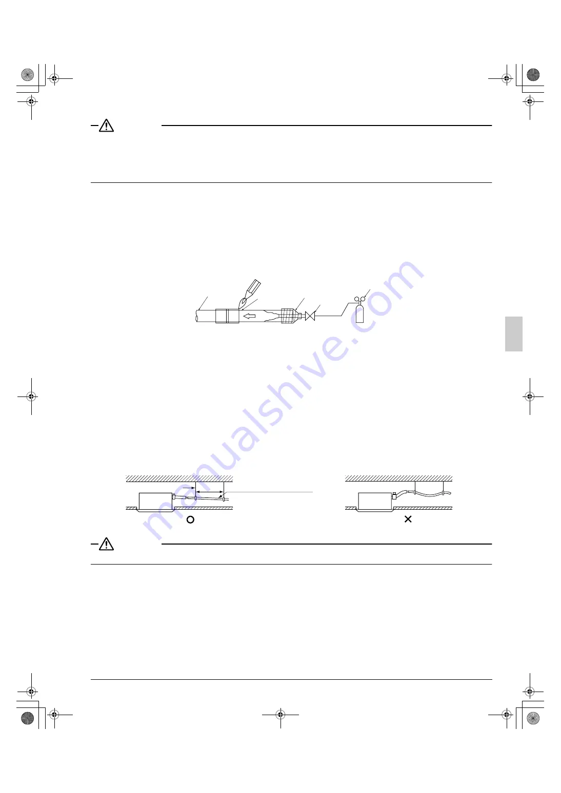
Nitrogen should be set to 2.9psi with a pressure-reducing valve if brazing while inserting nitrogen into the 
piping.

 (Refer to Fig. 17)

7. DRAIN PIPING WORK

(1)

Rig drain piping

As for drain work, perform piping in such a manner that water can be drained properly.

Employ a pipe with either the same diameter or with the diameter larger (excluding the raising section) than 
that of the connecting pipe (PVC pipe, nominal diameter 1in., outside diameter 1-1/4in.).

Keep the drain pipe short and sloping downwards at a gradient of at least 1/100 to prevent air pockets from 
forming.

If the drain pipe cannot be sufficiently set on a slope, execute the drain raising piping.

To keep the drain pipe from sagging, space hanger bracket every 3 to 5ft..

CAUTION

Water pooling in the drainage piping can cause the drain to clog.

Use the attached drain hose (1) and metal clamp (2).

Insert the drain hose into the drain socket up to the base, and tighten the metal clamp securely within the 
portion of a white tape of the hose-inserted tip. Tighten the metal clamp until the screw head is less than 
5/32in. from the hose.

Wrap the attached sealing pad (10) over the metal clamp and drain hose to insulate.

Nitrogen

Pressure-reducing valve

Hands valve

Taping

Refrigerant piping

Part to be
brazed 

Nitrogen

Fig. 17

1/100 gradient or more

3-5ft.

Fig. 18-1

GOOD

Hanger bracket

Fig. 18-2

WRONG

01_EN_3P161684-6K.fm  Page 13  Friday, September 16, 2011  10:00 PM

Summary of Contents for FCQ18PAVJU

Page 1: ...tions carefully before installation Keep this manual in a handy place for future reference Lire soigneusement ces instructions avant l installation Conserver ce manuel port e de main pour r f rence ul...

Page 2: ...jury WARNING Indicates a potentially hazardous situation which if not avoided could result in death or serious injury CAUTION Indicates a potentially hazardous situation which if not avoided may resul...

Page 3: ...g Before touching electrical parts turn off the unit Be sure to install a ground fault circuit interrupter if one is not already available This helps prevent electrical shocks or fire Securely fasten...

Page 4: ...nimals making contact with electrical parts can cause malfunctions smoke or fire Instruct the customer to keep the area around the unit clean NOTE Install the power supply and control wires for the in...

Page 5: ...air contains high levels of salt such as that near the ocean and where voltage fluctuates greatly such as that in factories Also in vehicles or vessels 2 ACCESSORIES Check the following accessories a...

Page 6: ...outdoor unit fully installed The unit may malfunction or the compo nents burn out Is the gas leak test finished It may result in insufficient cooling Is the unit fully insulated Condensate water may d...

Page 7: ...s approval which matches the following conditions A location from which cool warm air will reach the whole room A location with no objects blocking the air passage A location where drainage can be don...

Page 8: ...have to be shut off if two three or four corner shut off directions are selected See the shut off materials sold separately instal lation manual for details 4 Use suspension bolts for installation Ch...

Page 9: ...to 6 REFRIGERANT PIPING WORK 7 DRAIN PIPING WORK and 8 ELECTRIC WIRING WORK After making an opening in the ceiling it may be necessary to reinforce ceiling beams to keep the ceiling level and to prev...

Page 10: ...uilder or carpenter for details The center of the ceiling opening is indicated on the paper pattern for installation The center of the unit is indicated on the triangular mark to the unit bottom and o...

Page 11: ...and 1 3 in 1 For new ceilings 2 3 Perform steps 1 4 1 5 in 1 For new ceilings 6 REFRIGERANT PIPING WORK For refrigerant piping of outdoor units see the installation manual attached to the outdoor unit...

Page 12: ...ecting pipes to from the unit Refer to Fig 14 Refer to Table 3 for the dimensions of flare nut spaces When connecting the flare nut apply ester oil or ether oil to the flare section outside only and s...

Page 13: ...ine Exposed piping may cause condensation or burns on contact Pipe size Further tightening angle Recommended arm length of tool 1 4 60 to 90 degrees Approx 6in 3 8 60 to 90 degrees Approx 8in 1 2 30 t...

Page 14: ...ig 17 7 DRAIN PIPING WORK 1 Rig drain piping As for drain work perform piping in such a manner that water can be drained properly Employ a pipe with either the same diameter or with the diameter large...

Page 15: ...stall according to the procedure shown below Select converging drain pipes whose gauge is suitable for the operating capacity of the unit 2 After piping work is finished check if drainage flows smooth...

Page 16: ...ater into the drain pan through the blow off mouth on the left hand side of the drain socket Make sure not to pour water over the drain pump or any electric parts including those of the drain pump Whe...

Page 17: ...apable of shutting down power supply to the entire system must be installed Refer to the installation manual attached to the outdoor unit for the size of power supply electric wire con nected to the o...

Page 18: ...ound wire to the ground terminal In doing this pull the wires inside through the hole and fix the wires securely with the included clamp 4 2 points Remote controller wires not necessary for slave unit...

Page 19: ...ectrical external noise 5 For remote controller wiring refer to the INSTALLATION MANUAL OF REMOTE CONTROLLER attached to the remote controller 6 Never connect power supply wiring to the terminal block...

Page 20: ...rminal block for remote controller Control box cover P1 P2 Wiring diagram Backside of control box cover Remote controller wiring Power supply terminal block Insulation tube 16 3P Remote controller wir...

Page 21: ...er supply ground and other power wiring at least 2in so that they do not pass through the same place together Proximity may cause electrical interference malfunctions and breakage 9 2 Wiring example W...

Page 22: ...P2 F1 F2 T1 T2 Power supply 208 230V 1 60Hz Control box Outdoor unit Indoor unit Remote controller L1 L2 Fig 30 P1 P2 P1 P2 For use with 2 remote controllers L1L2 IN D OUT D F1 F2 F1 F2 P1 P2 F1 F2 T1...

Page 23: ...off the upper part The remote controller PC board is attached to the upper part of remote controller Refer to Fig 31 2 Turn the main sub changeover switch on one of the two remote controller PC board...

Page 24: ...11 FIELD SETTING and 12 TEST RUN first Refer to the installation manual attached to the decoration panel After installing the decoration panel ensure that there is no space between the unit body and...

Page 25: ...2 The figure of the ceiling height is for the all round outlet For the settings for four direction part of corner closed off three direction and two direction outlets see the installation manual supp...

Page 26: ...e 6 is displayed there may be a problem with the wiring or power supply so check the wiring again Table 6 If the decoration panel is installed on the indoor unit during the test run check the operatio...

Page 27: ...3P161684 6K EM11A061 1110 1645 Wallace Drive Suite 110 Carrollton TX 75006 USA info daikinac com www daikinac com HT 00_CV_3P161684 6K fm Page 2 Friday September 2 2011 4 00 PM...

Reviews: