D-EOMHP01405-21_02EN 18/35
3.12.1. Demand Limit
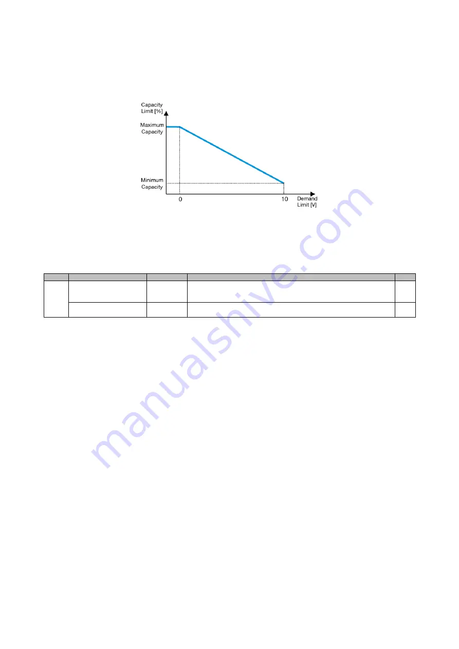
The “Demand limit” function allows the unit to be limited to a specified maximum load. Capacity limit level is regulated
using an external 0-10 V signal with a linear relationship shown in the picture below. A signal of 0 V indicates the maximum
capacity available whereas a signal of 10 V indicates the minimum capacity available.
Graph 2
– Demand Limit[V] vs Capacity Limit[%]
It is worth pointing out that it is not possible to shut down the unit using the demand limit function, but only to unload it to
its minimum capacity.
The option can be activated through the HMI Unit Interface in the menu [18] Power Conservation, parameter 00:
Menu
Parameter
Range
Description
R/W
18
00
(
Demand Limit
Enable
)
0-1
(Off-On)
Off = Demand Limit Disabled
On = Demand Limit Enabled
W
01
(
Current Lim Sp
)
0-200A
The maximum current limit that the unit can reach.
W
In order to enable this option in the HMI Web Interface, go to
Main Menu
→
Commission Unit
→
Configuration
→
Options
and set the
Demand Limit
parameter to Yes.
All info about this function are reported in the
Main Menu
→
View/Set Unit
→
Power Conservation
→
Demand Limit
page in the HMI Web Interface.
3.12.2. Current Limit
Current limit function allows to control unit power consumption taking current drawn below a specific limit.
In order to activate the function Current Limit, the user can set a Current Limit Setpoint lower than the Default value, defined
through the HMI or BAS communication.
The current limit uses a deadband centered around the actual limit value, such that unit capacity increase is not allowed
when current is within this deadband. If unit current is above the deadband, capacity is decreased until it is back within the
deadband. The current limit deadband is 5% of the current limit.
The Current Limit setpoint is accessible through the HMI, in the menu [18] Power Conservation, parameter 01 (refer to
previous paragraph).
All info about this function are reported in the
Main Menu
→
View/Set Unit
→
Power Conservation
→
Current Limit
page in the HMI Web Interface.
3.12.3. Setpoint Reset
The “Setpoint Reset” function can override the chiller water temperature active setpoint when certain circumstances occur.
The aim of this function is to reduce the unit energy consumption whilst maintaining the same comfort level. To this purpose,
three different control strategies are available:
•
Setpoint Reset by Outside Air Temperature (OAT)
•
Setpoint Reset by an external signal (0-10V)
•
Setpoint Reset by Evaporator ΔT (EWT)
In order to set the desired setpoint-reset strategy, go to the parameter group number [20
] “Setpoint Reset”, according to
the following table:


