background image


D-EOMHP01501-22_00EN 19/29 


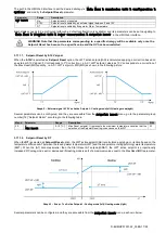
In order to use the DoS utility, the customer has to communicate the 

Serial Number

 to Daikin company and subscribe to the DoS 

service. Then, from this page, it is possible to: 


Start/Stop the DoS connectivity 


Check the connection status to DoS service 


Enable/Disable the remote update option 

 
In the unlikely event of UC replacement, the DoS connectivity can be switched from the old PLC to the new one just communicating 
the current 

Activation Key

 to Daikin company. 

 
The Daikin on Site (DoS) page can be accessed navigating through the HMI Web Interface, with path 

Main Menu


View/Set 

Unit


Daikin On Site

3.14.  Date/Time 

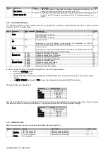
The unit controller can take stored the actual date and time, that are used for Scheduler, and can be modified going in [10] and 
[11] menu: 
 

Menu 

Parameter 

Range


Description


R/W 

10 

00 
(

Day

0…7 

Defines actual day stored in UC 

01 
(

Month

0…12 

Defines actual month stored in UC 

02 
(

Year

0..9999 

Defines actual year stored in UC 

11 

00 
(

Hour

0…24 

Defines actual hour stored in UC 

(

Minute

01 

0…60 

Defines actual minute stored in UC 

 
The Date/Time information can b

e found at path “

Main Menu


View/Set Unit


Date/Time

”. 


WARNING  Remember  to  check  periodically  the  controller  battery  in  order  to  maintain  updated  date  and 
time even when there is no electrical power. Refer to controller maintenance section. 


3.15.  Master/Slave 

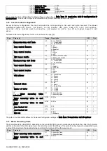
Master/Slave protocol integration requires the selection of the address for each unit that we want to control. In each system we 
can have only one master and 

a maximum of three slaves and it’s necessary to indicate the correct number of slaves. 

Address 

and 

Number of Units

 can be selected through the parameters [15.04] and [15.07]. 

 
Notice that Master/Slave is not compatible with 

Pump Control Mode

 VPF and DT. 

Menu 

Parameter 

Description 

R/W 

15 
(

Customer Configuration

08 
(

Address

0 = Standalone 
1 = Master 
2 = Slave1 
3 = Slave2 
4 = Slave3 

10 
(

Number of Units

0 = 2 Units 
1 = 3 Units 
2 = 4 Units 

 
Address  and  Number  of  Units  can  be  also  set  in  the  W

eb HMI path “

Main  Menu


Commission  Unit


Configuration


Options

”. 

 
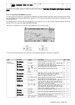
Master Slave parameter can be set in Page [16] and are available only in Master Unit: 
 

Menu 

Parameter 

Range 

R/W 

Psw 

[16] 
Master/Slave 
(Available only for Master Unit) 

[16.00] 

Start Up Limit


0-5 

[16.01] 

Shut Dn Limit


0-5 

[16.02] 

Stage Up Time


0-20 min 

[16.03] 

Stage Dn Time


0-20 min 

[16.04] 

Stage Up Load


30-100 

[16.05] 

Stage Dn Load


30-100 

[16.06] 

PrioSlave#1


1-4 

[16.07] 

PrioSlave#2


1-4 

[16.08] 

PrioSlave#3


1-4 

[16.09] 

MasterPriority


1-4 

[16.10] 

Master Enable


Off-On 

[16.11] 

Standby Chiller


None/Auto/Master/Slave1/Slave2/Slave3 

[16.12] 

Cycling Type


Run Hours/Sequence 

Summary of Contents for EWWQ-KC

Page 1: ...Water to water heat pump units with scroll compressors EWWQ KC EWLQ KC Original Instruction REV 00 Date 01 2022 Supersedes Operating Manual D EOMHP01501 22_00EN ...

Page 2: ...DeltaT 12 3 7 Network Control 13 3 8 Thermostatic Control 13 3 9 External Alarm 14 3 9 1 Thermostatic Source Control 14 3 9 1 1 Entering Water Temperature Control 14 3 9 1 2 Leaving Water Temperature Control 15 3 10 Unit Capacity 16 3 11 Power Conservation 16 3 11 1 Setpoint Reset 16 3 11 1 1 Setpoint Reset by 0 10V signal 17 3 11 1 2 Setpoint Reset by DT 17 3 12 Controller IP Setup 18 3 13 Daikin...

Page 3: ...uires to be accessed frequently the installation of a remote interface is strongly recommended LCD display of the unit controller may be damaged by extremely low temperatures see chapter 2 3 For this reason it is strongly recommended to never power off the unit during winter especially in cold climates 1 3 Avoid electrocution Only personnel qualified in accordance with IEC International Electrotec...

Page 4: ...nterface DSH Discharge Superheat MOP Maximum operating pressure DT Discharge Temperature SSH Suction Super Heat EEWT Evaporator Entering Water Temperature ST Suction Temperature ELWT Evaporator Leaving Water Temperature UC Unit controller POL468 85 MCQ MCQ EP Evaporating Pressure R W Readable Writable 2 2 Controller Operating Limits Operation IEC 721 3 3 Temperature 40 70 C Humidity 95 r h no cond...

Page 5: ...f one of following parameters Parameters Name 1 00 Unit Enable 1 01 Circuit 1 Enable 1 02 Circuit 2 Enable 2 00 Available Modes 4 00 Control Source da collegare in sapro se necessario 5 00 Cool Setpoint 1 5 01 Cool Setpoint 2 5 02 Heat Setpoint 1 5 03 Heat Setpoint 2 8 07 Evaporator Delta T setpoint 8 20 Condenser Delta T Setpoint 9 09 Thermostatic Source Control 13 00 DHCP Enable 14 03 Number of ...

Page 6: ...s f g 4 The interface has a multi level structure divided as follows Main Menu Parameters Sub Parameters Page 1 Parameter 1 00 Sub Parameter 1 0 0 Sub Parameter 1 0 XX Parameter 1 XX Sub Parameter 1 XX 0 Sub Parameter 1 XX YY Page 2 Parameter 2 00 Sub Parameter 2 0 0 Sub Parameter 2 0 XX Parameter 2 XX Sub Parameter 2 XX 0 Sub Parameter 2 XX YY Page N Parameter N 00 Sub Parameter N 00 0 Sub Parame...

Page 7: ...ctioning mode Chiller Running in cooling mode LED Functioning mode Heat Pump Running in heat mode LED Compressor ON Circuit 1 Left Circuit 2 Right Compressor ON Compressor OFF Compressor performing preopen or pump down procedure LED Circulation Pump ON Pump ON Pump OFF C LED Temperature Temperature Value displayed Bar LED Pressure Pressure Value displayed LED Percentage Percentage Value displayed ...

Page 8: ... W Psw 17 Scheduler Scheduler 17 00 Monday Monday 17 0 0 Time 1 W 1 17 0 1 Value 1 W 1 17 0 2 Time 2 W 1 17 0 3 Value 2 W 1 17 0 4 Time 3 W 1 17 0 5 Value 3 W 1 17 0 6 Time 4 W 1 17 0 7 Value 4 W 1 17 01 Tuesday Tuesday 17 1 0 Time 1 W 1 17 1 1 Value 1 W 1 17 1 2 Time 2 W 1 17 1 3 Value 2 W 1 17 1 4 Time 3 W 1 17 1 5 Value 3 W 1 17 1 6 Time 4 W 1 17 1 7 Value 4 W 1 17 02 Wednesday Wednesday 17 2 0...

Page 9: ...ring and the Value related to Time is set for all minutes of the selected hours of the day 3 3 3 Network On Off Chiller On Off can be managed also with BACnet or Modbus RTU communication protocol To control the unit over the network follow below instructions 1 Unit On Off switch closed 2 Unit Enable Enable refer to 3 3 1 3 Control Source 1 refer to 3 7 The HMI menu is Menu Parameter Range R W 04 0...

Page 10: ... setpoint W 02 Heat LWT 1 20 C 55 C Primary heating setpoint W 03 Heat LWT 1 20 C 55 C Secondary heating setpoint W The change between primary and secondary setpoint can be performed using the Double setpoint contact available with accessory EKRSCBMS or through the Scheduler function Double setpoint contact works as below Contact opened the primary setpoint is selected Contact closed the secondary...

Page 11: ...ed water temperature below 4 C is required or glycol is present in the water circuit 3 5 1 Heat Cool Mode Heat Cool operating mode can be set using a Digital Input All settings related to Cooling Heating operation will produce a real mode change only if Unit Mode parameter refer to menu 01 is set to Heat Cool Heat Cool w Glycol In all other cases no mode switch will be allowed Menu Parameter Range...

Page 12: ... Pump Run Hours 1 0 99999 Evaporator Operation Hours R 1 10 Evap Pump Run Hours 2 0 99999 Evaporator Operation Hours R 1 11 Evap Pump Mode Auto Manual Pump mode This parameter allows to switch the control of the pump to a fixed speed W 1 12 Evap Manual Speed 0 100 Manual Pump Speed Pump speed when the manual mode is selected W 1 13 Evap Thermo Off Stanby Speed 0 100 Pump Speed in Thermostat Off Un...

Page 13: ...he controlled temperature is higher Cool Mode or lower Heat Mode than the active setpoint of at least a Start Up DT value whereas second compressor when available is started if the controlled temperature is higher Cool Mode or lower Heat Mode than the active setpoint AS of at least a Stage Up DT SU value Compressors stop if performed following same procedure looking to the parameters Stage Down DT...

Page 14: ...ntact is the following Contact state Alarm State Note Opened Alarm The alarm is generated if the contact remains opened for at least 5 seconds Closed No Alarm The alarm is reset just the contact is closed The configuration is performed from Page 15 as shown below Menu Parameter Range Description 15 09 Ext Alarm 0 No External Alarm disabled 1 Event Event configuration generates an alarm in the cont...

Page 15: ...d stop does not exceed safety limit 2 Reduced amount of compressor Start Stop Less accurate Thermostatic Control To reduce amount of compressor start stop customer can modify the StartupDT parameter according to following indication 𝑆𝑡𝑎𝑟𝑡𝑈𝑝𝐷𝑇 𝑁𝑜𝑚𝑖𝑛𝑎𝑙 𝐷𝑇 𝑁𝑢𝑚𝑏𝑒𝑟 𝑜𝑓 𝑈𝑛𝑖𝑡 𝐶𝑜𝑚𝑝𝑟𝑒𝑠𝑠𝑜𝑟𝑠 Parameter Description Value Control Temperature Leaving Water Temperature SP Based on Leaving Water Temperature Startup...

Page 16: ...nu View Set Circuit Circuit 1 or Circuit 2 Data Main Menu View Set Circuit Circuit 1 or Circuit 2 Compressors 3 11 Power Conservation In this chapters will be explained the functions used to reduce the unit power consumption 3 11 1 Setpoint Reset The Setpoint Reset function can override the chiller water temperature active setpoint when certain circumstances occur The aim of this function is to re...

Page 17: ...o a correction of the Max Reset MR quantity i e AS LWT setpoint MR MR as shown in the following picture Graph 2 External signal 0 10V vs Active Setpoint Cooling mode left Heating mode right Several parameters can be configured and they are accessible from the Setpoint Reset menu go to the parameter group number 16 Setpoint Reset according to the following table Menu Parameter Range Description R W...

Page 18: ...third field of IP Address W 03 IP 4 Defines the fourth field of IP Address W 04 Manual Mask 00 Msk 1 Defines the first field of Mask W 01 Msk 2 Defines the second field of Mask W 02 Msk 3 Defines the third field of Mask W 03 Msk 4 Defines the fourth field of Mask W In order to modify the MTIV IP Network configuration do the following operations access the Settings menu set the DHCP option to Off m...

Page 19: ...er to maintain updated date and time even when there is no electrical power Refer to controller maintenance section 3 15 Master Slave Master Slave protocol integration requires the selection of the address for each unit that we want to control In each system we can have only one master and a maximum of three slaves and it s necessary to indicate the correct number of slaves Address and Number of U...

Page 20: ... Condenser Pump Ctrl Mode 0 3 0 On Off Mode 1 Fixed Speed 3 DeltaT Mode W 1 05 Cond Control Measure 0 2 0 No 1 CondIn 2 CondOut W 1 06 Cond Control Device 0 2 0 No 1 Valve 2 VFP W 1 07 SCM Address 0 4 0 Standalone 1 Master 2 Slave1 3 Slave2 4 Slave3 W 1 08 External Alarm 0 3 0 No 1 Event 2 Rapid Stop W 1 09 Number of Units 0 2 0 2 Units 1 3 Units 2 4 Units W 1 10 Water Reversing Valve Behaviour 0 ...

Page 21: ...e bus W 1 02 Mb Parity 0 Even 1 Odd 2 None Defines the parity used in Modbus communication and must be identical for all nodes of the bus W 1 03 Mb 2StopBit Off 1 Stop Bit On 2 Stop Bits Defines whether 2 stop bits should be used W 1 04 Mb Timeout 0 10 Defines the timeout in second for the response of the slave before a communication error is reported W 1 05 BN Address 1 255 Defines UC address in ...

Page 22: ...ctual Water Setpoint Page 2 String Up Unit Capacity String Dn Unit Mode To exit the Screen Saver menu it s necessary to press any of four HMI button The interface will come back to Page 0 3 21 Generic Controller Operation The main controller operations available are Application Save and Apply Changes The first one is used to save the current configuration of parameters in the UC in order to avoid ...

Page 23: ...A R 1 08 03 Max Speed N A W 1 08 04 Min Speed N A W 1 08 05 Speed 1 N A W 1 08 06 Parameter Ti N A W 1 08 07 Setpoint DT N A W 1 08 08 Evap DT N A R 1 08 09 Evap Pump Run Hours 1 N A R 1 08 10 Evap Pump Run Hours 2 N A R 1 08 11 Evap Pump Mode N A W 1 08 12 Evap Manual Speed N A W 1 08 13 Evap Thermo Off Standby Sp N A W 1 08 14 Cond Standby Spd N A W 1 08 15 Cond Pump Speed CondVfpOut N A R 1 08 ...

Page 24: ... N A W 1 15 04 Cond Pump Control Mode N A W 1 15 05 Cond Ctrl Meas N A W 1 15 06 Cond Ctrl Dev N A W 1 15 07 Address N A W 1 15 08 Ext Alarm N A W 1 15 09 Master Slave Number of Units N A W 1 15 10 WRV Behaviour N A W 1 15 11 WRV Cool Delay N A W 1 15 12 WRV Heat Delay N A W 1 15 13 Evap Nominal DT N A W 1 15 14 Cond Nominal DT N A W 1 15 15 HMI Select N A W 1 16 Master Slave Available only for Ma...

Page 25: ...1 20 01 Max Reset DT N A W 1 20 02 Start Reset DT N A W 1 19 Protocol Communication 22 00 Mb Address N A W 1 22 01 Mb BAUD N A W 1 22 02 Mb Parity N A W 1 22 03 Mb 2StopBit N A W 1 22 04 Mb Timeout N A W 1 22 05 BN Address N A W 1 22 06 BN BAUD N A W 1 22 07 BN Device ID X XXX N A W 1 22 08 BN Device ID XXX N A W 1 22 9 BN Port X N A W 1 22 10 BN Port X XXX N A W 1 22 11 BN Timeout N A W 1 22 12 L...

Page 26: ...codes for parameter 7 00 is Alarm Type HMI Code Mapping Alarm Cause Solution Unit U001 UnitOff ExtEvent External signal mapped as Event detected by UC Check customer external signal source U003 UnitOff EvapFlowLoss Water circuit malfunction Check that water flow is possible open all valves in the circuit Check wiring connection Contact your local dealer U004 UnitOff EvapFreeze Water temperature un...

Page 27: ...tion is available in the paths Main Menu Alarms Alarm List 4 2 Troubleshooting If one of the following malfunctions occur take the measures shown below and contact your dealer WARNING Stop operation and shut off the power if anything unusual occurs burning smells etc Leaving the unit running under such circumstances may cause breakage electric shock or fire Contact your dealer The system must be r...

Page 28: ...D EOMHP01501 22_00EN 28 29 Notes ...

Page 29: ...se of its content and the products and services presented therein Specification are subject to change without prior notice Refer to the data communicated at the time of the order Daikin Applied Europe S p A explicitly rejects any liability for any direct or indirect damage in the broadest sense arising from or related to the use and or interpretation of this publication All content is copyrighted ...

Reviews: