Daikin EWLQ Series Installation, Maintenance & Operating Manual Download Page 15

D-EIMWC01206-15EN - 15/20 


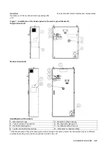
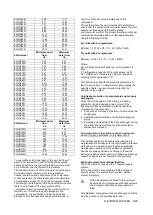
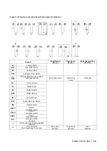
Figure 5 - Wiring for connecting the unit at the place of installation 


Legend 

Conditioning 

Version 

Heat Pump 

Version 

Moto-Evaporating 

Version 

AI 

Analog Inputs


A.R. 

ON / OFF remote


AO 

Analog Output


CFS 

Condenser Flow Switch 

CP-

VFD 

VFD (Variable Frequency Drive) 

condenser pump


VFD 3 Way Valve 


VFD 3 Way 

Valve


VFD Fans


D.L. 

Limit of charge


DI 

Digital Inputs


DO 

Digital Outputs


DPS 

Digital Setpoint


EF 

External Fault 

EFS 

Evaporator Flow Switch


GA 

General Alarm 

KPC-1 

Pump 1 

condenser water


KPC-2 

Pump 2 

condenser water


KPE-1 

Pump 1 

evaporator water 

S.O. 

Exclusion of the 

set point


HP Version only (Cooling-Heating 

Remote)


VFD # 2 ON-OFF 

(Moto-Evaporating Version only)


Tower Fans 

ON/OFF


Tower Fans 

ON/OFF


Fans 

ON/OFF


Summary of Contents for EWLQ Series

Page 1: ...manual EWWQ090G EWWQ720L Water cooled scroll chillers EWLQ090G EWLQ720L Condenserless EWHQ100G EWHQ400G Heat pump scroll chillers Refrigerant R410A D EIMWC01206 15EN REV 00 Date Supersedes EWLQ G L C...

Page 2: ...unit can be seasonally inverted General Information All the units are delivered together withwiring diagrams certifieddrawings nameplateandDoC DeclarationofConformity Thesedocumentslistallthe technica...

Page 3: ...t Identification of the labels 1 Manufacturer s logo 5 Hazardous voltage warning 2 Type of coolant in the circuit s 6 Non flammable gas symbol 3 Electrical hazard symbol 7 Identification data of the u...

Page 4: ...ency Service wait without leaving the injured person alone until the rescue operators come Give all necessary information to the rescue operators Positioning and assembly The unit must be installed on...

Page 5: ...he unit very slowly keeping it perfectly level Avoid bumping and or shaking the unit during the handling and loading unloading operations from the transportation vehicle push or pull the unit only usi...

Page 6: ...re 4 Handling of the double circuit unit Alternative handling method 1 Remove before installation 2 Use lifting hooks with closing device exclusively The hooks must be safely fastened before performin...

Page 7: ...es not exceed the design pressure of the water side heat exchangers and install a safety valve on the pipe of the water 12 Install a suitable expansion CAUTION To avoid damages install a filter that c...

Page 8: ...onsible for any damages or malfunctions of the equipment The quality of the water must comply with the specifications listed in the following table Circulating water Water supply Possible problems Ele...

Page 9: ...installed must therefore ensure that the overall content of water allows the unit t operate continuously and therefore greater environmental comfort The minimum water content per unit must be calculat...

Page 10: ...other components of the system or other appliances in general 2 Plan an electrical circuit for the connection of the unit This circuit must be protected with the necessary safety devices that is a ma...

Page 11: ...quence and operation of all the safety devices The user must keep a log system booklet of the operating data of the unit installed and of all the periodic maintenance and service activities If the ope...

Page 12: ...ranty All the units are tested at the factory and guaranteed for a specific period of time These units have been developed and constructed according to high quality standards ensuring years of failure...

Page 13: ...stalled in an aggressive environment perform this activity monthly The following are considered aggressive environments place with high concentration of industrial exhaust gas in the air Place close t...

Page 14: ...collection centres This manual is a technical aid and does not represent a binding offer We cannot guarantee explicitly or implicitly the completeness accuracy or reliability of its contents All data...

Page 15: ...requency Drive condenser pump VFD 3 Way Valve VFD 3 Way Valve VFD Fans D L Limit of charge DI Digital Inputs DO Digital Outputs DPS Digital Setpoint EF External Fault EFS Evaporator Flow Switch GA Gen...

Page 16: ...e A Typical single refrigerant circuit The input and output of the water of the condenser and the evaporator are approximate Consult the dimensional drawings of the unit for the exact hydraulic connec...

Page 17: ...Figure B Typical single refrigerant circuit of the moto evaporating version The input and output of the water of the evaporator are approximate Consult the dimensional drawings of the unit for the exa...

Page 18: ...Figure C Typical single refrigerant circuit for Heat Pump The input and output of the water of the condenser and the evaporator are approximate Consult the dimensional drawings of the unit for the exa...

Page 19: ...r 17 Refrigerant inlet connection from the remote condenser 18 Condenser leaving water connection 19 Condenser entering water connection 20 Evaporator leaving water connection 21 Evaporator entering w...

Page 20: ...cy reliability or fitness for particular purpose of its content and the products and services presented therein Specifications are subject to change without prior notice Daikin Europe N V explicitly r...

Reviews: