


EWAQ016~ EWYQ016~064BAW
Packaged air-cooled water chiller
4PW70082-1C – 2013.07
Installation and operation manual
10
4.5.
Perform the water piping work
4.5.1.
Connecting the water pipes
Water connections must be made in accordance with all applicable
legislations and the outlook drawing delivered with the unit,
respecting the water in- and outlet.
If dirt gets in the water circuit, problems may occur. Therefore, always
take into account the following when connecting the water circuit:
■
Use clean pipes only.
■
Hold the pipe end downwards when removing burrs.
■
Cover the pipe end when inserting it through a wall so that no
dust and dirt enter.
■
Use a good thread sealant for the sealing of the connections.
The sealing must be able to withstand the pressures and
temperatures of the system, it must also be resistant to the used
glycol in the water.
■
When using non-brass metallic piping, make sure to insulate
both materials from each other to prevent galvanic corrosion.
■
Make sure to provide a proper drain for the pressure relief valve.
■
Because brass is a soft
material, use appropriate tooling
for connecting the water circuit.
Inappropriate tooling will cause
damage to the pipes.
■
For correct operation of the
system, a regulating valve must
be installed in the water system.
The regulating valve is to be used to regulate the water flow in
the system (field supply).
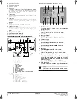
4.5.2.
Installing the shut-off valve kit
Refer to figure 12.
1
Adapter piece
2
Shut-off valve
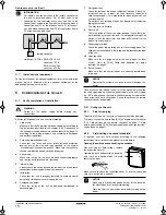
4.5.3.
Insulating the water pipes
The complete water circuit, inclusive all piping, must be insulated to
prevent condensation during cooling operation and reduction of the
heating and cooling capacity as well as prevention of freezing of the
outside water piping during winter time. The thickness of the sealing
materials must be at least 13 mm with
λ
=0.039 W/mK in order to
prevent freezing of the outside water piping at ambient temperature
of –15°C.
If the temperature is higher than 30°C and the humidity is higher than
RH 80%, then the thickness of the sealing materials should be at
least 20 mm in order to avoid condensation on the surface of the
sealing.
4.5.4.
Check the water volume and expansion vessel
pre-pressure
The unit is equipped with an expansion vessel of 12 litre which has a
default pre-pressure of 1 bar.
To assure proper operation of the unit, the pre-pressure of the
expansion vessel might need to be adjusted and the minimum and
maximum water volume must be checked.
1
Check that the minimum total water volume in the installation,
excluding the internal water volume of the unit, is according to
the table.
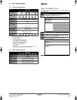
Refer to "6.1. Technical specifications" on page 24 to know the
internal water volume of the unit.
2
Calculating the pre-pressure of the expansion vessel
The pre-pressure (Pg) to be set depends on the maximum
installation height difference (H) and is calculated as below:
Pg=(H/10+0.3) bar
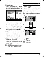
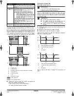
3
Checking the maximum allowed water volume
To determine the maximum allowed water volume in the entire
circuit, proceed as follows:
1
Determine for the calculated pre-pressure (Pg) the
corresponding maximum water volume using the graph
below.
2
Check that the total water volume in the entire water circuit is
lower than this value.
If this is not the case, the expansion vessel inside the unit is too
small for the installation. Solution: Install an additional expansion
vessel in the field piping.
figure "Maximum allowed water volume"
NOTICE
Be careful not to deform the unit piping by using excessive
force when connecting the piping.
NOTICE
■
The unit is only to be used in a closed water system.
Application in an open water circuit can lead to
excessive corrosion of the water piping.
■
Never use Zn-coated parts in the water circuit.
Excessive corrosion of these parts may occur as
copper piping is used in the unit's internal water
circuit.
EWAQ
Minimum
total water
volume (l)
EWYQ
Minimum total water volume
(l)
Cooling
Cooling
Heating
016
33
016
33
76
021
33
021
33
76
025
33
025
33
76
032
33
032
33
110
040
66
040
66
152
050
66
050
66
152
064
66
064
66
220
INFORMATION
In most applications this minimum water volume will have a
satisfying result.
In critical processes or in rooms with a high heat load
though, extra water volume might be required.
pre-pressure
= pre-pressure
maximum volume
= maximum volume (water or water + glycol)
A
= system without glycol
B
= system with 20% propylene glycol
C
= Default
(Refer to Caution: "Use of glycol" on page 11)
C
0.3
0.5
1
1.5
2
2.5
100
50
0
34
150
200
250
300
350
400
450
[l]
maximum volume
[bar]
pre-pressure
B
A
500
B
A
4PWEN70082-1C.book Page 10 Wednesday, September 25, 2013 7:31 AM
Summary of Contents for EWAQ016BAW
Page 47: ......


