


Installation and operation manual
9
EWAQ016~ EWYQ016~064BAW
Packaged air-cooled water chiller
4PW70082-1C – 2013.07
8.
Water inlet connection
9.
Water outlet connection
10.
Drain and fill valve
11.
Water filter
The water filter removes dirt from the water to prevent damage
to the pump or blockage of the evaporator. The water filter must
be cleaned on a regular base. See "5.5. Service and
maintenance" on page 23.
12.
Pressure gauge
The pressure gauge allows readout of the water pressure in the
water circuit.
13.
Flow switch
The flow switch checks the flow in the water circuit and protects
the heat exchanger against freezing and the pump against
damage.
14.
Pump
The pump circulates the water in the water circuit.
15.
Pressure relief valve
The pressure relief valve prevents excessive water pressure in
the water circuit by opening at 3 bar and discharging some
water.
16.
Entry for power supply (PS)
17.
Entry for high voltage wiring (HV)
18.
Entry for low voltage wiring (LV)
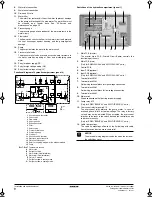
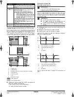
Functional diagram of hydraulic compartment (panel 3)
1
Shut-off valve water outlet
2
Check valve
3
Flow switch
4
Air purge valve
5
Expansion vessel
6
Filter
7
Safety valve
8
Pressure relief valve
9
Pressure gauge
10
Drain port
11
Shut-off valve water inlet
12
Electronic expansion valve
13
Plate heat exchanger
14
Refer to the piping diagram of the outdoor module
15
Pump
R11T~R14T
Temperature sensors
A
Water side
B
Refrigerant side
C
Water outlet (field installation)
D
Water inlet (field installation)
E
Only for P-models
F
Refrigerant flow in cooling mode
G
Refrigerant flow in heating mode
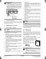
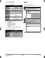
Switch box of the hydraulic compartment (panel 1)
1.
Main PCB (master)
The master main PCB (Printed Circuit Board) controls the
functioning of the unit.
2.
Main PCB (slave)
(Only for EWAQ040~064* and EWYQ040~064* units.)
3.
Control PCB
4.
Input PCB (optional)
5.
Input PCB (optional)
(Only for EWAQ040~064* and EWYQ040~064* units.)
6.
Terminal block X1M
7.
Terminal block X2M
Field wiring terminal block for high voltage connection.
8.
Terminal block X3M
Field wiring terminal block for low voltage connection.
9.
Terminal block X4M
10.
Main switch
Allows connection of field wiring for power supply.
11.
Pump relay K1P
(Only for EWAQ*BAW(P/H)* and EWYQ*BAW(P/H)* units.)
12.
Overcurrent relay for pump K1S
The overcurrent relay protects the pump motor in case of
overload, phase failure or too low voltage. The relay is factory
set and may not be adjusted. When activated, the overcurrent
relay has to be reset in the switch box and the controller needs
to be reset manually.
(Only for EWAQ*BAW(P/H)* and EWYQ*BAW(P/H)* units.)
13.
Cable tie mountings
The cable tie mountings allow to fix the field wiring with cable
ties to the switch box to ensure strain relief.
1
11
5
9
2
6
12
7
13
2
3
4
14
R11T
R14T
R12T
R13T
A
B
C
D
E
EWAQ*P*, EWYQ*P*,
EWAQ*H*, EWYQ*H*
EWAQ*N*,
EWYQ*N*,
6
8
10
15
10
F
G
NOTICE
The electrical wiring diagram can be found on the inside of
the switch box cover.
2
3
6
8
7
10
12
9
4
5
1
11
13
4PWEN70082-1C.book Page 9 Wednesday, September 25, 2013 7:31 AM
Summary of Contents for EWAQ016BAW
Page 47: ......