


EWAQ+EWYQ009~0 EWAQ+EWYQ009~013ACW1
Packaged air-cooled water chillers and packaged
reversible air to water heatpumps
4PW51587-1A
Installation manual
24
Symptom 5: The water pressure relief valve leaks
Symptom 6: The user interface displays "
n
n
n
n
" when pressing
certain buttons
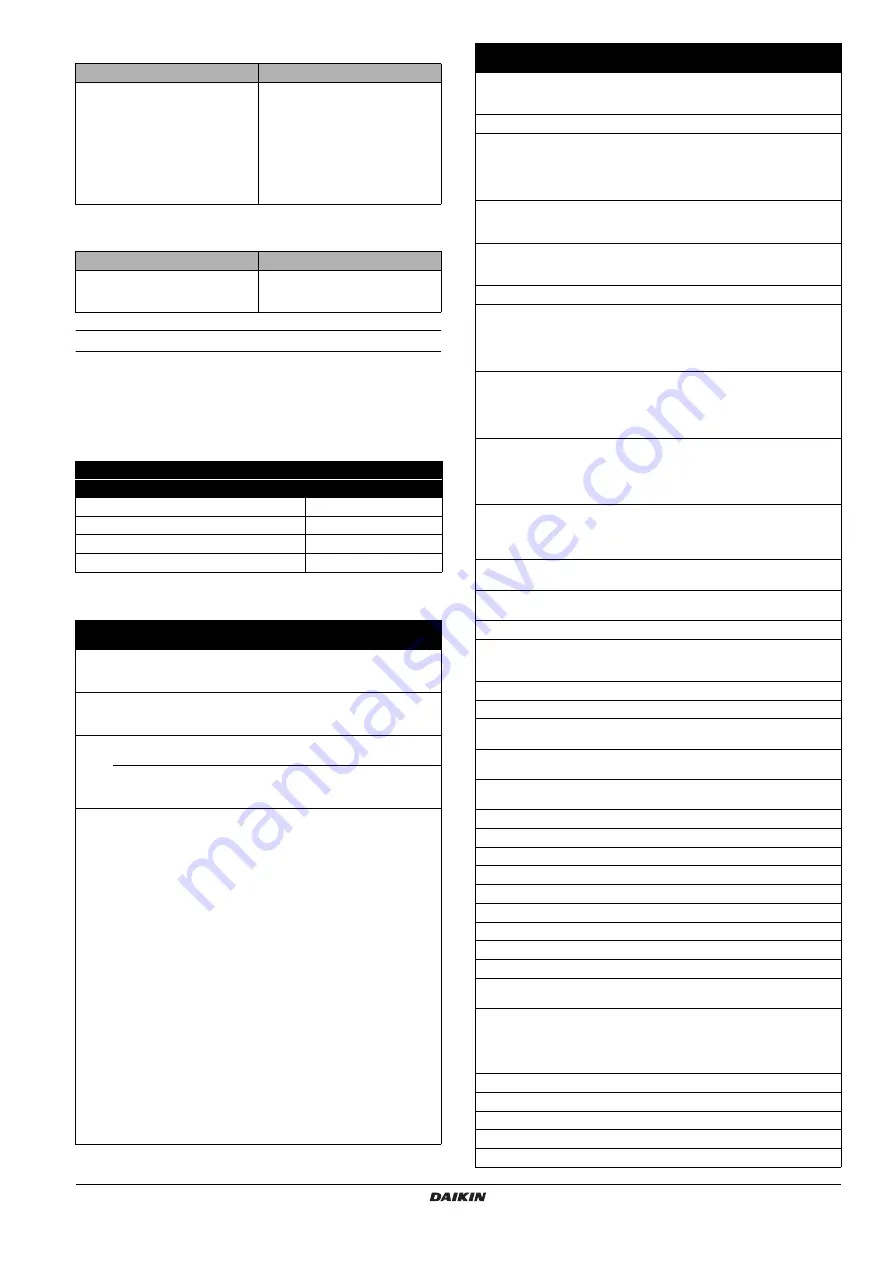
Error codes
When a safety device is activated, the user interface LED will be
flashing, and an error code will be displayed.
A list of all errors and corrective actions can be found in the table
below.
Reset the safety by turning the unit OFF and back ON.
In case this procedure for resetting the safety is not successful,
contact your local dealer.
P
OSSIBLE
CAUSES
C
ORRECTIVE
ACTION
Dirt is blocking the water pressure
relief valve outlet.
Check for correct operation of the
pressure relief valve by turning the
red knob on the valve counter
clockwise:
• If you do not hear a clacking sound,
contact your local dealer.
• In case the water keeps running out
of the unit, close both the water inlet
and outlet shut-off valves first and
then contact your local dealer.
P
OSSIBLE
CAUSES
C
ORRECTIVE
ACTION
The current permission level is set to
a level that prevents using the
pressed button.
Change the "user permission level"
field setting ([0-00], see
Instruction to turn the unit OFF
User interface mode (heating/cooling
=
)
Push the
y
button
ON
1 time
ON
1 time
OFF
—
OFF
—
Error
code
Failure cause
Corrective action
80
Inlet water temperature
thermistor failure (inlet water
thermistor broken)
Contact your local dealer.
81
Outlet water temperature
thermistor failure (outlet water
temperature sensor broken)
Contact your local dealer.
89
Water heat exchanger freeze-up
failure (due to water flow too low)
Refer to error code
7H
.
Water heat exchanger freeze-up
failure (due to refrigerant
shortage)
Contact your local dealer.
7H
Flow failure (water flow too low
or no water flow at all, minimum
required water flow is 16 l/min)
• Check that all shut off valves of
the water circuit are completely
open.
• Check if the water filter needs
cleaning.
•
Check that the unit is
operating within its operating
range (refer to
• Also refer to
• Make sure there is no air in the
system (purge air).
• Check on the manometer that
there is sufficient water
pressure. The water pressure
must be >0.3 bar (water is cold),
>>0.3 bar (water is hot).
• Check that the pump speed
setting is on the highest speed.
• Make sure that the expansion
vessel is not broken.
• Check that the resistance in the
water circuit is not too high for
the pump (refer to
).
• Check that the pump fuse (FU2)
and PCB fuse (FU1) are not
blown.
8H
Outlet water temperature of unit
too high (>65°C)
Check that the outlet water
thermistor is giving the correct
read out.
A1
Hydraulic PCB defective
Contact your local dealer.
A5
Too low (during cooling
operation) or too high (during
heating operation) refrigerant
temperature (measured by
R13T)
Contact your local dealer.
C0
Flow switch failure (flow switch
remains closed while pump is
stopped)
Check that the flow switch is not
clogged with dirt.
C4
Heat exchanger thermistor
failure (heat exchanger
temperature sensor broken)
Contact your local dealer.
E1
Compressor PCB defective
Contact your local dealer.
E3
Abnormal high pressure
Check that the unit is operating
within its operating range (refer
to
).
Contact your local dealer.
E4
Actuation of low pressure sensor
Check that the unit is operating
within its operating range (refer
to
).
Contact your local dealer.
E5
Overload activation of
compressor
Check that the unit is operating
within its operating range (refer
to
).
Contact your local dealer.
E7
Fan lock failure (fan is locked)
Check if the fan is not obstructed
by dirt. If the fan is not
obstructed, contact your local
dealer.
E9
Malfunction of electronic
expansion valve
Contact your local dealer.
F3
Too high discharge temperature
(e.g. due to coil blockage)
Clean the coil. If the coil is clean,
contact your local dealer.
H3
Malfunctioning HPS system
Contact your local dealer.
H9
Outdoor temperature thermistor
failure (outdoor thermistor is
broken)
Contact your local dealer.
J1
Malfunction of pressure sensor
Contact your local dealer.
J3
Discharge pipe thermistor failure
Contact your local dealer.
J5
Suction pipe unit thermistor
failure
Contact your local dealer.
J6
Aircoil thermistor frost detection
failure
Contact your local dealer.
J7
Aircoil thermistor mean
temperature failure
Contact your local dealer.
J8
Liquid pipe unit thermistor failure
Contact your local dealer.
L4
Electric component failure
Contact your local dealer.
L5
Electric component failure
Contact your local dealer.
L8
Electric component failure
Contact your local dealer.
L9
Electric component failure
Contact your local dealer.
LC
Electric component failure
Contact your local dealer.
P1
PCB failure
Contact your local dealer.
P4
Electric component failure
Contact your local dealer.
PJ
Failure of capacity setting
Contact your local dealer.
U0
Refrigerant failure (due to
refrigerant leak)
Contact your local dealer.
U1
Power supply cables are
connected in the reverse phase
instead of the normal phase.
Connect the power supply
cables in normal phase. Change
any two of the three power
supply cables (L1, L2, L3) to
correct phase.
U2
Main circuit voltage failure
Contact your local dealer.
U4
Communication failure
Contact your local dealer.
U5
Communication failure
Contact your local dealer.
U7
Communication failure
Contact your local dealer.
UA
Communication failure
Contact your local dealer.
Error
code
Failure cause
Corrective action
Summary of Contents for EWAQ-ACV3
Page 29: ...NOTES NOTES ...


