ESIE10-01
Functional Control
Part 2 – Functional Description
2–41
3
2
4
5
1
2.3.1
Circuit Control Logic
Circuit availability
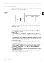
A circuit should be available to start if the following conditions are true:
■
Circuit switch is closed.
■
No circuit alarms are active.
■
Circuit Mode set point is set to Enable.
■
BMS Circuit Mode set point is set to Auto.
■
No cycle timers are active.
■
Discharge Temperature is at least 5°C higher than Oil Saturated Temperature.
Starting
The circuit should start if all these conditions are true:
■
Adequate pressure in the evaporator and condenser (see No Pressure At Start Alarm).
■
Circuit Switch is closed.
■
Circuit Mode set point is set to Enable.
■
BMS Circuit Mode set point is set to Auto.
■
No cycle timers are active.
■
No alarms are active.
■
Staging logic requires this circuit to start.
■
Unit state is Auto.
■
Evaporator pump state is Run.
■
Circuit Startup Logic
Circuit startup is the time period following the starting of the compressor on a circuit. During the
startup, the low evaporator pressure alarm logic should be ignored. When the compressor has
been running at least 20 seconds and the evaporator pressure rises above the low evaporator
pressure unload set point, the startup is complete.
If the pressure does not rise above the unload set point and the circuit has been running longer
than the Startup Time set point, then the circuit should be turned off and an alarm triggered. If the
evaporator pressure drops below the absolute low pressure limit then the circuit should be turned
off and the same alarm triggered.
■
Low OAT Restart Logic
Low OAT restart logic allows multiple start attempts in low ambient conditions. If the condenser
saturated temperature is less than 60 F when the compressor starts, the startup is considered to
be a 'low OAT start'. If a low OAT start is not successful the circuit shall shut down, but no alarm
should be triggered for the first two attempts of the day. If a third low OAT start attempt fails, then
the circuit should shut down and the Low OAT Restart Alarm should be triggered.
The restart counter should be reset when either a startup is successful, the Low OAT Restart
alarm is triggered, or the unit time clock shows that a new day has started.
Summary of Contents for EWAD620-C17C-SL
Page 2: ......
Page 8: ...ESIE10 01 1 2 Part 1 System Outline 3 1 1 5 ...
Page 111: ...ESIE10 01 General Outline Part 1 System Outline 1 105 3 1 4 5 1 36 1 Power Compressor 1 2 ...
Page 112: ...General Outline ESIE10 01 1 106 Part 1 System Outline 3 1 1 4 5 1 36 2 Power Compressor 3 ...
Page 113: ...ESIE10 01 General Outline Part 1 System Outline 1 107 3 1 4 5 1 36 3 Kit Pumps ...
Page 122: ...General Outline ESIE10 01 1 116 Part 1 System Outline 3 1 1 4 5 1 36 12 Digital Inputs Board ...
Page 123: ...ESIE10 01 General Outline Part 1 System Outline 1 117 3 1 4 5 1 36 13 Digital Outputs Board ...
Page 124: ...General Outline ESIE10 01 1 118 Part 1 System Outline 3 1 1 4 5 1 36 14 Digital Outputs Board ...
Page 131: ...ESIE10 01 General Outline Part 1 System Outline 1 125 3 1 4 5 1 36 21 EEXV Compressor 1 ...
Page 134: ...General Outline ESIE10 01 1 128 Part 1 System Outline 3 1 1 4 5 1 36 24 EEXV Compressor 2 ...
Page 137: ...ESIE10 01 General Outline Part 1 System Outline 1 131 3 1 4 5 1 36 27 EEXV Compressor 3 ...
Page 138: ...General Outline ESIE10 01 1 132 Part 1 System Outline 3 1 1 4 5 1 36 28 Pumps Control ...
Page 139: ...ESIE10 01 General Outline Part 1 System Outline 1 133 3 1 4 5 1 36 29 Terminals M1 M2 ...
Page 140: ...General Outline ESIE10 01 1 134 Part 1 System Outline 3 1 1 4 5 1 36 30 Terminals M3 ...
Page 141: ...ESIE10 01 General Outline Part 1 System Outline 1 135 3 1 4 5 1 36 31 Terminals M5 MQ ...
Page 148: ...General Outline ESIE10 01 1 142 Part 1 System Outline 3 1 1 4 5 ...
Page 150: ...ESIE10 01 2 2 Part 2 Functional Description 3 1 2 5 ...
Page 170: ...The Digital Controller ESIE10 01 2 22 Part 2 Functional Description 3 1 2 4 5 ...
Page 200: ...Functional Control ESIE10 01 2 52 Part 2 Functional Description 3 1 2 4 5 ...
Page 202: ...ESIE10 01 3 2 Part 3 Troubleshooting 3 1 3 5 ...
Page 254: ...Alarms and Events ESIE10 01 3 54 Part 3 Troubleshooting 3 1 3 4 5 ...
Page 266: ...Controller Inputs and Outputs ESIE10 01 3 66 Part 3 Troubleshooting 3 1 3 4 5 ...
Page 280: ...ESIE10 01 4 2 Part 4 Commissioning and Test Run 3 1 4 5 ...
Page 286: ...Pre Test Run Checks ESIE10 01 4 8 Part 4 Commissioning and Test Run 3 1 4 5 ...
Page 289: ...ESIE10 01 Running Data Part 4 Commissioning and Test Run 4 11 3 4 5 1 ...
Page 290: ...Running Data ESIE10 01 4 12 Part 4 Commissioning and Test Run 3 1 4 5 ...


