background image

5 Operation

Operation manual

7

ETVH/X16S(U)18+9W + ETBH/9W
Daikin Altherma 3 H HT F+W
4P644732-1 – 2021.02

5.1

User interface: Overview

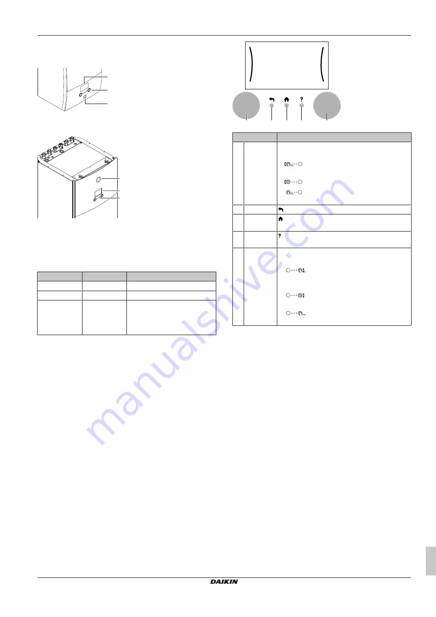
The user interface has the following components:

b

c

a

a

Status indicator

b

LCD screen

c

Dials and buttons

a

b

c

a

Status indicator

b

LCD screen

c

Dials and buttons

Status indicator

The  LEDs  of  the  status  indicator  light  up  or  blink  to  show  the
operating mode of the unit.

LED

Mode

Description

Blinking blue

Standby

The unit is not in operation.

Continuous blue Operation

The unit is in operation.

Blinking red

Malfunction

A malfunction occurred.

See 

"8.1 To display the help text

in case of a malfunction"

 [

4

 18]

for more information.

Slot for WLAN cartridge

With the WLAN cartridge, the installer can connect the system to the
internet.  As  user  you  can  then  control  the  system  via  the  Daikin
Residential  Controller  app. 

Note: 

This  slot  cannot  be  used  for  SD

cards.

USB connector

With a USB memory stick, the installer can:

▪ Update the software. This requires a correct config file on the USB

memory stick.

▪ Import  the  settings  generated  by  E-Configurator  (Heating

Solutions  Navigator)  from  the  USB  memory  stick  to  the  user
interface  (MMI).  This  requires  a  correct  config  file  on  the  USB
memory stick.

▪ Export  the  current  settings  (i.e.  field  settings,  MMI  EEPROM

settings,  schedule  timers)  from  the  user  interface  (MMI)  to  the
USB memory stick.

LCD screen

The  LCD  screen  has  a  sleeping  function.  After  15  min  of  non-
interaction with the user interface, the screen darkens. Pressing any
button or rotating any dial awakens the display.

Dials and buttons

You use the dials and buttons:

▪ To navigate through the screens, menus and settings of the LCD

screen

▪ To set values

a

b

c

d

e

Item

Description

a

Left dial

The LCD shows an arc on the left side of the
display when you can use the left dial.

:  Turn,  then  press  the  left  dial.  Navigate

through the menu structure.

: Turn the left dial. Choose a menu item.

: Press the left dial. Confirm your choice

or go to a submenu.

b

Back button

: Press to go back 1 step in the menu structure.

c

Home
button

: Press to go back to the home screen.

d

Help button

: Press to show a help text related to the current

page (if available).

e

Right dial

The LCD shows an arc on the right side of the
display when you can use the right dial.

: Turn, then press the right dial. Change

a value or setting, shown at the right side of the
screen.

:  Turn  the  right  dial.  Navigate  through

the possible values and settings.

:  Press  the  right  dial.  Confirm  your

choice and go to the next menu item.

Summary of Contents for ETVH16S23EA6V

Page 1: ...rma 3 H HT F W English Operation manual Daikin Altherma 3 H HT F W ETVH16S U 18EA6V ETVH16S U 23EA6V ETVH16S18EA9W ETVH16S23EA9W ETVX16S18EA6V ETVX16S23EA6V ETVX16S18EA9W ETVX16S23EA9W ETBH16EF6V ETBH...

Page 2: ...onfiguration wizard 20 11 2 Settings menu 20 1 About this document Thank you for purchasing this product Please Read the documentation carefully before operating the user interface to ensure the best...

Page 3: ...appliance Cleaning and user maintenance SHALL NOT be made by children without supervision WARNING To prevent electrical shocks or fire Do NOT rinse the unit Do NOT operate the unit with wet hands Do...

Page 4: ...or collectors Before you purge air from heat emitters or collectors check if or is displayed on the home screen of the user interface If not you can purge air immediately If yes make sure that the ro...

Page 5: ...control the protection is NOT guaranteed NOTICE Water pipe freeze prevention Even if you turn OFF space heating cooling operation C 2 Operation Space heating cooling water pipe freeze prevention if e...

Page 6: ...ing water temperature Possible actions on this screen Go through the temperatures Change the temperature Go to the next temperature Confirm changes and proceed More information For more information se...

Page 7: ...user interface MMI This requires a correct config file on the USB memory stick Export the current settings i e field settings MMI EEPROM settings schedule timers from the user interface MMI to the USB...

Page 8: ...5 Setpoint range Heating minimum Heating maximum Cooling minimum Cooling maximum 7 2 Time date Hours Minutes Year Month Day Daylight savings time Format 7 3 Holiday Activation From Till 7 4 Quiet Acti...

Page 9: ...y Heat pump failure and system operates in Emergency mode or heat pump is forced off d Current date and time e Smart energy e1 Smart energy is available via solar panels or smart grid e2 Smart energy...

Page 10: ...erature 2 Main zone Shows the applicable symbol for your main zone emitter type Set the leaving water temperature for the main zone 3 Additional zone Restriction Only displayed if there are two leavin...

Page 11: ...ating cooling operation ON b Space heating cooling operation OFF Tank heating operation 1 6 bar 55 21 35 45 c 1 6 bar 55 21 35 45 d c Tank heating operation ON d Tank heating operation OFF 5 4 2 To tu...

Page 12: ...one of the following options Heating Only heating mode Cooling Only cooling mode Automatic The operation mode changes automatically between heating and cooling based on the outdoor temperature Restric...

Page 13: ...to produce hot water is at night because the space heating demand is lower Example t 60 C 00 00 07 00 50 C 15 C 40 C 14 00 21 00 1 2 3 4 5 Tt Tt DHW tank temperature t Time Initially the DHW tank temp...

Page 14: ...temperature control is active you can program the main zone schedule instead 1 Go to the schedule 2 optional Clear the content of the whole week schedule or the content of a selected day schedule 3 Pr...

Page 15: ...each character of the schedule name 4 To name the current schedule browse through the character list and confirm the selected character The schedule name can contain up to 15 characters 5 Confirm the...

Page 16: ...erature Go to the next temperature Confirm changes and proceed 5 9 3 Slope offset curve Slope and offset Define the weather dependent curve by its slope and offset Change the slope to differently incr...

Page 17: ...g 2 6 Main zone Cooling WD curve Additional zone Heating 3 5 Additional zone Heating WD curve Additional zone Cooling 3 6 Additional zone Cooling WD curve Zone Go to Tank Restriction Only available to...

Page 18: ...on on fluorinated greenhouse gases requires that the refrigerant charge of the unit is indicated both in weight and CO2 equivalent Formula to calculate the quantity in CO2 equivalent tonnes GWP value...

Page 19: ...er production When Emergency is set to Manual and a heat pump failure occurs the domestic hot water heating and space heating stops To manually recover it via the user interface go to the Malfunctioni...

Page 20: ...em Indoor unit type read only Backup heater type 9 3 1 read only Domestic hot water 9 2 1 Emergency 9 5 Number of zones 4 4 Glycol Filled system overview field setting E 0D Booster heater capacity 9 4...

Page 21: ......

Page 22: ......

Page 23: ......

Page 24: ...4P644732 1 2021 02 Copyright 2021 Daikin 4P644732 1 0000000O Verantwortung f r Energie und Umwelt...

Reviews: