7 Installation
Installer reference guide
41
ERGA04~08DAV3(A) + EHVH/X04+08S18+23DA
Daikin Altherma – Low temperature split
4P495248-1 – 2017.12
Typical workflow
Connecting the electrical wiring typically consists of the following
stages:
1
Making sure the power supply system complies with the
electrical specifications of the heat pump.
2
Connecting the electrical wiring to the outdoor unit.
3
Connecting the electrical wiring to the indoor unit.
4
Connecting the main power supply.
5
Connecting the backup heater power supply.
6
Connecting the shut–off valves.
7
Connecting the electrical meters.
8
Connecting the domestic hot water pump.
9
Connecting the alarm output.
10
Connecting the space cooling/heating ON/OFF output.
11
Connecting the changeover to an external heat source.
12
Connecting the power consumption digital inputs.
13
Connecting the safety thermostat.
7.9.2
About electrical compliance
Only for ERGA04~08DAV3 (not for ERGA04~08DAV3A)
Equipment complying with EN/IEC 61000‑3‑12 (European/
International Technical Standard setting the limits for harmonic
currents produced by equipment connected to public low-voltage
systems with input current >16 A and ≤75 A per phase.).
Only for the backup heater of the indoor unit
See
"7.9.9 To connect the backup heater power supply" on
page 44
.
7.9.3
Precautions when connecting the
electrical wiring
INFORMATION
Also read the precautions and requirements in the
following chapters:
▪ General safety precautions
▪ Preparation
DANGER: RISK OF ELECTROCUTION
WARNING
ALWAYS use multicore cable for power supply cables.
7.9.4
Guidelines when connecting the electrical
wiring
Keep the following in mind:
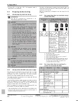
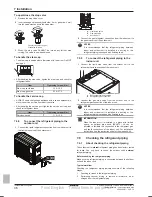
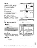
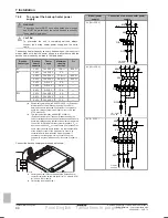
▪ If stranded conductor wires are used, install a round crimp-style
terminal on the end of the wire. Place the round crimp-style
terminal on the wire up to the covered part and fasten the terminal
with the appropriate tool.
b
a
a
Stranded conductor wire
b
Round crimp-style terminal
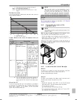
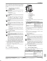
▪ Use the following methods for installing wires:
Wire type
Installation method
Single-core wire
c b
c
a
a
A
AA´
A´
a
Curled single-core wire
b
Screw
c
Flat washer
Stranded conductor
wire with round
crimp-style terminal
c b
b
a
c
a
B
B
a
Terminal
b
Screw
c
Flat washer
O
Allowed
X
NOT allowed
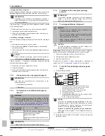
Tightening torques
Item
Tightening torque (N•m)
M4 (X1M)
1.2~1.5
M4 (earth)
7.9.5
Specifications of standard wiring
components
Component
06DAV3
ERGA08DAV3
ERGA04~08D
AV3A
Power
supply
cable
MCA
(a)
19.9 A
24.0 A
15.9 A
Voltage
230 V
Phase
1~
Frequen
cy
50 Hz
Wire
sizes
Must comply with applicable legislation
Interconnection
cable
Minimum cable section of 1.5 mm² and
applicable for 230 V
Recommended
field fuse
20 A
25 A
16 A
Earth leakage
circuit breaker
Must comply with applicable legislation
(a)
MCA=Minimum circuit ampacity. Stated values are
maximum values (see electrical data of combination with
indoor units for exact values).
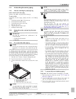
7.9.6
To connect the electrical wiring on the
outdoor unit
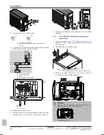
1
Remove the switch box cover.
Final English - Tanslations in progress

