background image

9

SYSTEM OPERATION

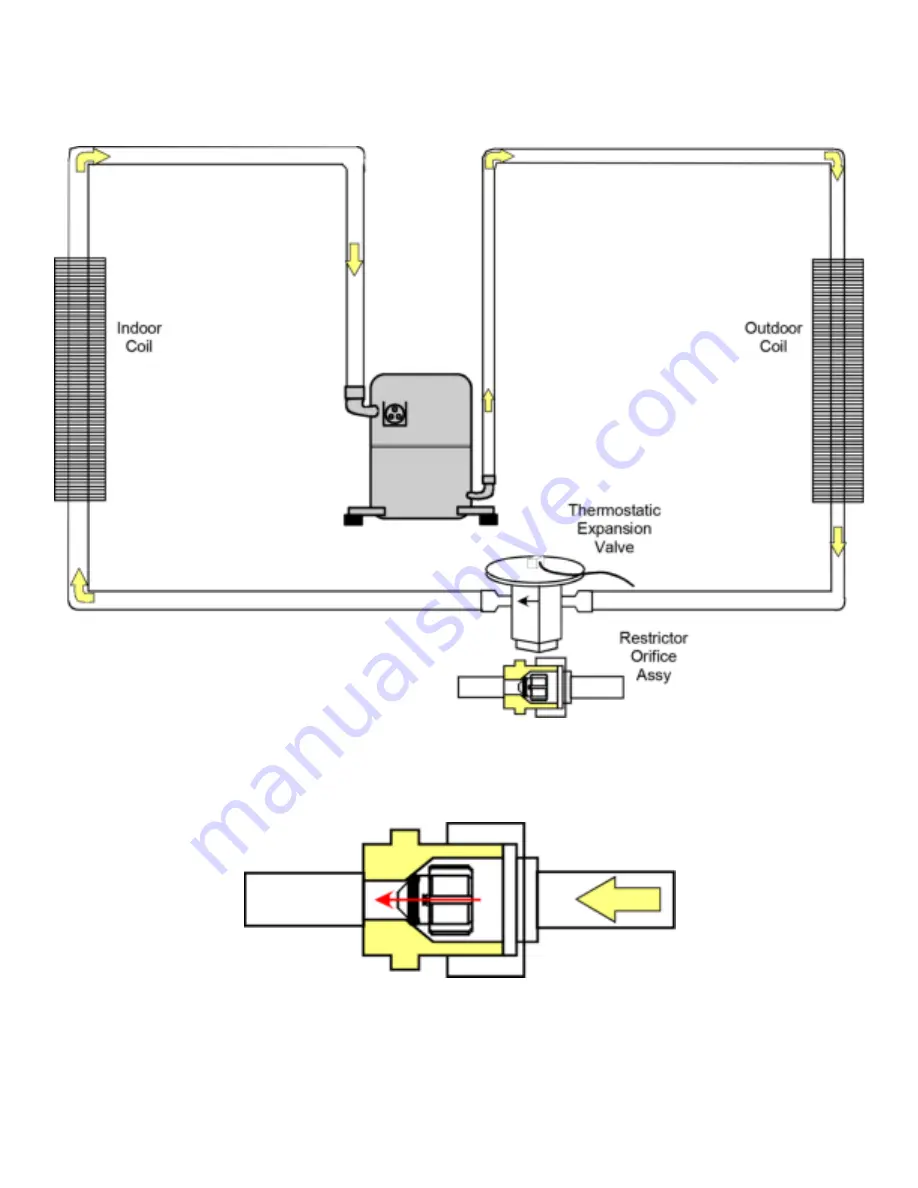
Typical Package Cooling or Package Gas 

Either a thermostatic expansion valve or restrictor orifice assembly may be used depending on model, refer to the parts 

catalog for the model being serviced. 

Restrictor Orifice Assembly in Cooling Operation

In the cooling mode, the orifice is pushed into its seat forcing refrigerant to flow through the metered hole in the center 

of the orifice. 

Summary of Contents for DP14UM

Page 1: ...EEN TRAINED TO INSTALL ADJUST SERVICE OR REPAIR HEREINAFTER SERVICE THE EQUIPMENT SPECIFIED IN THIS MANUAL SHOULD SERVICE THE EQUIPMENT THE MANUFACTURER WILL NOT BE RESPONSIBLE FOR ANY INJURY OR PROPERTY DAMAGE ARISING FROM IMPROPER SERVICE OR SERVICE PROCEDURES IF YOU SERVICE THIS UNIT YOU ASSUME RESPONSI BILITY FOR ANY INJURY OR PROPERTY DAMAGE WHICH MAY RESULT IN ADDITION IN JURISDICTIONS THAT ...

Page 2: ...cold To avoid possible frostbite or blindness avoid contact with refrigerant and wear gloves and goggles If liquid refrigerant does contact your skin or eyes seek medical help immediately Always follow EPA regulations Never burn refrigerant as posionous gas will be produced WARNING To avoid possible injury explosion or death practice safe handling of refrigerants WARNING The compressor POE oil for...

Page 3: ... 000 BTU H 80 000 BTU H 24 2 tons 30 2 tons 36 3 tons 14 14 SEERR D P 14 U M 24 060 4 1 A A 1 2 3 4 5 6 7 8 9 10 11 12 13 14 15 Engineering Brand Minor revision D Daikin Engineering Major revision Product Type Voltage P Packaged 1 208 230V single phase 60 Hz SEER Refrigerant 4 R 410A Nominal Heat Input Unit Type Tonnage Nominal 040 40 000 BTU H 16 16 SEERR 42 2 tons 48 3 tons 61 5 tons U Ultra Low...

Page 4: ...aikin Brand Ultra Low Nox Package Gas 14 Seer R410A Multi Position gas electric units Initial release of single phase models DP16UM 30 36 41AA Daikin Brand Ultra Low Nox Package Gas 16 Seer R410A Multi Position gas electric units Initial release of single phase models Single Phase Package Gas Units ...

Page 5: ... heated gas into the outdoor condenser coil In the condenser coil the hot refrigerant gas being warmer than the outdoor air first loses its superheat by heat transferred from the gas through the tubes and fins of the coil The refrigerant now becomes saturated part liquid part vapor and then continues to give up heat until it condenses to a liquid alone Once the vapor is fully liquefied it continue...

Page 6: ...ntacts close initiating a call for heat Integrated control module performs safety circuit checks Pressure Sensor Verification The control operates the inducer in a manner to verify the pressure sensor null value and span operation are within specification If the system is operating correctly this test takes only a few seconds If the system is not functioning properly the control times out after a ...

Page 7: ...XPIRED RED 1 HOUR OR HARD LOCKOUT STEADY ON OEM FACTORY TEST MODE AMBER N A RAPID FLASH FIELD TEST MODE AMBER N A 1 FLASH LOW FLAME SENSE AMBER N A 2 FLASHES ID PLUG FAILURE AMBER HARD LOCKOUT HEATING MODE 3 FLASHES CONTROL FUSE OPEN AMBER 5 MINUTES STEADY ON STANDBY NORMAL OPERATION NO THERMOSTAT CALL GREEN N A RAPID FLASH CLEAR ERROR HISTORY GREEN N A 1 FLASH CALL FOR HEATING GREEN N A 2 FLASHES...

Page 8: ...lled onto the board Please see the instructions below 1 Select the appropriate ID plug for the installed model number from the table above 2 Attached the appropriate ID plug for the installed model number to the control board into the blue connector as shown below This will load the correct parameters to the board Failure to follow these instructions will result in the board not functioning ...

Page 9: ...restrictor orifice assembly may be used depending on model refer to the parts catalog for the model being serviced Restrictor Orifice Assembly in Cooling Operation In the cooling mode the orifice is pushed into its seat forcing refrigerant to flow through the metered hole in the center of the orifice ...

Page 10: ...ogen or nitrogen traced 24 S 102 Evacuation 24 S 103 Charging 25 S 104 Checking Compressor Efficiency 26 S 105 Thermostatic Expansion Valve 26 S 106 Overfeeding 26 S 107 Underfeeding 27 S 108 Superheat 27 S 109 Checking Subcooling 27 S 110 Checking expansion valve operation 28 S 111 Fixed Orifice Restrictor Devices 28 S 112 Checking Restricted Liquid Line 28 S 113 Overcharge Of Refrigerant 29 S 11...

Page 11: ...ing Multiple power sources may be present Failure to do so may cause property damage personal injury or death 1 Check wiring visually for signs of overheating damaged insulation and loose connections 2 Use an ohmmeter to check continuity of any suspected open wires 3 If any wires must be replaced replace with comparable gauge and insulation thickness S 3 Checking Thermostat and Wiring Thermostat W...

Page 12: ...r and other relay holding coils are wired into the low or line voltage circuits When the control circuit is energized the coil pulls in the normally open contacts or opens the normally closed contacts When the coil is de energized springs return the contacts to their normal position NOTE Most single phase contactors break only one side of the line L1 leaving 115 volts to ground present at most int...

Page 13: ... capacitor motor The capacitors primary function is to reduce the line current while greatly improving the torque characteristics of a motor This is accomplished by using the 90 phase relationship between the capacitor current and voltage in conjunction with the motor windings so that the motor will give two phase operation when connected to a single phase circuit The capacitor also reduces the li...

Page 14: ...ng Testing Capacitor Resistance 2 Set an ohmmeter on its highest ohm scale and connect the leads to the capacitor A Good Condition indicator swings to zero and slowly returns to infinity Start capacitor with bleed resistor will not return to infinity It will still read the resistance of the resistor B Shorted indicator swings to zero and stops there replace C Open no reading replace Start capacito...

Page 15: ...otor shell If the ohmmeter indicates continuity to ground the motor is defective and must be replaced 5 Using an ohmmeter check the windings for continuity pin to pin If no continuity is indicated the thermal limit over load device may be open Allow motor to cool and retest Motor Connector 3 pin Motor OK when R 100k ohm 3 pin Winding Test Checking Eem Motors The EEM motor is a one piece fully enca...

Page 16: ... board 5 If line voltage is present reinsert the 5 pin connector and remove the 16 pin connector 6 Check for signal 24 volts at the transformer 7 Check for signal 24 volts from the thermostat to the G terminal at the 16 pin connector 8 Using an ohmmeter check for continuity from the 1 3 common pins to the transformer neutral or C thermostat terminal If you do not have continuity the motor may func...

Page 17: ...ing potentially severe or fatal injury to anyone in its path This discharge can be ignited external to the compressor if the terminal cover is not properly in place and if the discharge impinges on a sufficient heat source Ignition of the discharge can also occur at the venting terminal or inside the compressor if there is sufficient contaminant air present in the system and an electrical arc occu...

Page 18: ...all power legs are open 1 Carefully remove the compressor terminal protective cover and inspect for loose leads or insulation breaks in the lead wires 2 Disconnect the three leads going to the compressor terminals at the compressor or nearest point to the compressor 3 Check for a ground separately between each of the three terminals and ground such as an unpainted tube on the compressor If there i...

Page 19: ... other connector again reads infinity Reverse polarity on the ohmmeter leads and repeat The female connector that read infinity previously should now read close to zero ohms C Replace plug if either of these test methods doesn t show the desired results S 17D Operation Test If the voltage capacitor overload and motor winding test fail to show the cause for failure WARNING High Voltage Disconnect a...

Page 20: ...ngs 3 Remove all burrs and clean the brazing surfaces of the tubing with sand cloth or paper Brazing materials do not flow well on oxidized or oily surfaces 4 Clean the inside of all new tubing to remove oils and pipe chips 5 When brazing sweep the tubing with dry nitrogen to prevent the formation of oxides on the inside surfaces 6 Complete any repair by replacing the liquid line drier in the syst...

Page 21: ... the shut off valve to the high vacuum gauge manifold only After the compound gauge low side has dropped to approximately 29 inches of vacuum open the valve to the vacuum thermocouple gauge See that the vacuum pump will blank off to a maximum of 25 microns A high vacuum pump can only produce a good vacuum if its oil is non contaminated LOW SIDE GAUGE AND VALVE HIGH SIDE GAUGE AND VALVE Evacuation ...

Page 22: ...r Due to their design Scroll compressors are inherently more tolerant of liquid refrigerant NOTE Even though the compressor section of a scroll compressor is more tolerant of liquid refrigerant continued floodback or flooded start conditions may wash oil from the bearing surfaces causing premature bearing failure S 104 Checking Compressor Efficiency The reason for compressor inefficiency is broken...

Page 23: ...uration temperature corresponding to its pressure The degree of superheat equals the degrees of temperature increase above the saturation temperature at existing pressure See Temperature Pressure Chart on following page CAUTION To prevent personal injury carefully connect and disconnect manifold gauge hoses Escaping liquid refrigerant can cause burns Do not vent refrigerant to atmosphere Recover d...

Page 24: ...e 109 F To obtain the amount of subcooling subtract 109 F from 120 F The difference is 11 subcooling See the specification sheet or technical information manual for the design subcooling range for your unit S 110 Checking expansion valve operation 1 Remove the remote bulb of the expansion valve from the suction line 2 Start the system and cool the bulb in a container of ice water closing the valve...

Page 25: ...g device could allow liquid refrigerant to return to the compressor under extreme overcharge conditions Also with a fixed orifice restrictor device flowrator metering device extreme cases of insufficient indoor air can cause icing of the indoor coil and liquid refrigerant return to the compressor but the head pressure would be lower There are other causes for high head pressure If other causes che...

Page 26: ...vacuate and recharge system 6 Start up the unit and record the pressure drop across the drier 7 Continue to run the system for a minimum of twelve 12 hours and recheck the pressure drop across the drier Pressure drop should not exceed 6 PSIG 8 Continue to run the system for several days repeatedly checking pressure drop across the suction line drier If the pressure drop never exceeds the 6 PSIG th...

Page 27: ... Primary Limit Control APG GPG units use a snap disk type primary limit device Sometimes referred to as stat on a stick The limit setting is fixed and must not be readjusted in the field Testing Primary Limit Control Refer to the specification section to determine the proper limit cutout temperature for the model being serviced In all instances the limit control is wired in series with the ignitio...

Page 28: ...open Push the red reset button test again if still open replace the control Testing Auxiliary Limit Control S 302 Checking Flame Rollout Switch DP14UM DP16UM units are equipped with a temperature activated manual reset control This control is mounted to the manifold assembly and is wired in series with the auxiliary limit and gas valve The control is designed to open should a flame roll out occur ...

Page 29: ...resent Failure to do so may cause property damage personal injury or death 1 Disconnect the motor wire leads from its connection point at integrated ignition control module 2 Using and ohmmeter test for continuity between each of the motor leads 3 Touch one probe of the ohmmeter to the motor frame ground and the other probe in turn to each lead If the windings do not test continuous or a reading i...

Page 30: ...ounted near induced draft blower Its function is to regulate the induced draft blower s speed in order to maintain proper air fuel ratio for clean and reliable combustion The pressure sensor also guards against insufficient airflow combustion air and flue products through the heat exchanger The pressure sensor should read approximately 2 5 in w c for the 40 000 BTU hr models 2 2 in w c for the 60 ...

Page 31: ...e and or rollout causing burning in the burner venturi If delayed ignition should occur the following should be checked 1 Improper gas pressure adjust to proper pressure Improper burner positioning burners should be in locating slots level front to rear and left to right 2 Carry over lighter tube or cross lighter obstructed clean 3 Main burner orifice s deformed or out of alignment to burner repla...

Page 32: ...ontrol and place in heating cycle 7 As the unit fires on high stage the manometer negative pressure will drop to 1 0 0 3 W C 8 If not as listed replace control NOTE The pressure switch must be mounted with the diaphragm in a vertical position S 314 Checking Flame Sensor A flame sensing device is used in conjunction with the ignition control module to prove combustion If a microamp signal is not pr...

Page 33: ...10 If no reading check for continuity on all components and if good replace ignition control module NOTE Contaminated fuel or combustion air can create a nearly invisible coating on the flame sensor This coating works as an insulator causing a loss in the flame sense signal If this situation occurs the flame sensor must be cleaned with steel wool Do not use sandpaper the silicone in sandpaper will...

Page 34: ...PAN ERROR RED 5 MINUTES Inducer not maintaining pressure setting Check pressure sensor hose for blocked or pinched hose or improper connection Check wiring connections Replace pressure sensor if faulty 4 FLASHES HIGH LIMIT SWITCH OPEN RED MAXIMUM RECOVERY TIME 1 HOUR AFTER MAX TRIPS EXCEEDED Primary limit or auxiliary limit circuit is open Check circulator blower speed and performance Check filter...

Page 35: ...for proper sensor alignment Clean flame rod Compare gas pressure to rating plate info Adjust as needed 2 FLASHES ID PLUG FAILURE AMBER HARD LOCKOUT HEATING MODE Improper ID plug Replace ID plug 3 FLASHES CONTROL FUSE OPEN AMBER 5 MINUTES Blown fuse Inspect wiring for damage mis wiring or short to ground Replace integrated control module fuse 3A STEADY ON STANDBY NORMAL OPERATION NO THERMOSTAT CALL...

Page 36: ...TOR TON ON DELAY TIMER RELAY TR TRANSFORMER VM VENT MOTOR WIRE COD E BLACK BLUE BROWN GREEN GRAY ORANGE PINK PURPLE RED TAN WHITE YELLOW BK BL BR GR GY OR PK PU RD TN WH YL HIGH VOLTAGE LOW VOLTAGE OPTIONAL HIGH VOLTAGE OPTIONAL LOW VOLTAGE CHASSIS GROUND FIELD W IR ING FACTOR Y WIR ING HIGH VOLTAGE LOW VOLTAGE EARTH GROUND 0140G04555 A PLS BTS ALS PU PU PU ALS PLM PLF PU PU 2 1 2 1 YL RD RD YL BL...

Page 37: ...YL OR C L G N BK PU BL GR PU BK T1 T2 T3 T4 T5 M 1 YL WH EM FS YL BL RD GND TON t 180s R1 Y1 BL Y2 R2 YL 3 5 4 3 2 1 YL LINE VOLTAGE 208 230V 3PH 60Hz R C S RD L1 L2 HPS GR COM TR BR RD BL BK RD BK RD YL OR BR YL OR BR YL WH BL WH BK OR YL BR 1 2 BK WH VM GR GR CCH GR GR GR GR 3 YL WH T3 L3 FC CM GR BR BK PU BR RD BK BK PU M 1 J5 PLM 3A G R W Y C 5 4 3 2 1 1 TO THERMOSTAT 5 4 3 2 1 5 4 3 2 1 6 6 8...

Page 38: ... IGN YL OR C L G N BK PU BL GR PU BK T1 T2 T3 T4 T5 M 1 EM FS YL RD TON t 180s R1 Y1 BL Y2 R2 PU 3 5 4 3 2 1 YL G R W Y C 5 4 3 2 1 GR COM TR BR PU RD BK RD YL OR BR WH BK OR YL BR 2 BK WH VM GR BL HPS LPS PU YL OR BR PU BL RD BL PU PU PU GND LINE VOLTAGE 208 230V 3PH 60Hz 1 5 4 3 2 1 5 4 3 2 1 6 6 8 7 8 7 9 9 PLF PLM ECON BL PU PU YL PU GR RD RD BL ALS AUXILIARY LIMIT SWITCH BTS BURNER TEMPERATUR...

Page 39: ...LUG CONNECTOR PLM MALE PLUG CONNECTOR PLS PRIMARY LIMIT SWITCH RC RUN CAPACITOR TON ON DELAY TIMER RELAY TR TRANSFORMER VM VENT MOTOR PSS PSG PS VCC PLI NC BTS NC BTS PLO GV RETURN TR 24 VAC TR GND GV OUTPUT PLM 12 11 10 9 8 7 6 5 4 3 2 1 FLAME ROD T7 COOL FAN HEAT FAN J5 PCBBL216 9 8 7 6 5 4 3 2 1 12 11 10 J8 1 2 3 3 2 1 J4 IDC 20 VDC I PWM C I RPM F PLM FAN PLM DSI 5 4 3 2 1 L2 L2 L1 GND J3 5 4 ...

Page 40: ...NDENSER MOTOR COMP COMPRESSOR CS COMP SOLENOID 2ND STG COOLING EM EVAPORATOR MOTOR FS FLAME SENSOR GND EQUIPMENT GROUND GPT GAS PRESSURE TRANSDUCER GV GAS VALVE HPS HIGH PRESSURE SWITCH IGN IGNITOR PLF FEMALE PLUG CONNECTOR PLM MALE PLUG CONNECTOR PLS PRIMARY LIMIT SWITCH RC RUN CAPACITOR TON ON DELAY TIMER RELAY TR TRANSFORMER VM VENT MOTOR VSTB VARIABLE SPEED TERMINAL BLOCK 4 PLS ALS PU PU PU AL...

Page 41: ...ll piping and etc for refrigerant leaks 8 Check the combustion chamber Heat Exchanger for soot scale etc Inspect all burners for lint and proper positioning 9 Start the system using the proper instrumentation check gas inlet and manifold pressures burner flame and microamp signal Adjust if necessary 10 Start the system and run a Heating Performance Test If the results of the test are not satisfact...

Page 42: ... CFH 6 Check with your local utility for actual BTU content caloric value of natural gas in the area the average is 1025 BTU s 7 Use this formula to calculate the BTU HR input See BTU HR Calculation Example Cubic Feet per Hour CFH x BTU content of your natural gas BTU HR input 8 Should the figure you calculated not fall within five 5 percent of the nameplate rating of the unit adjust the gas valve...

Page 43: ...43 SCHEDULED MAINTENANCE Table 2 ...

Reviews: