


16
V
ENT
/F
LUE
AND
C
OMBUSTION
A
IR
P
IPE
T
ERMINATIONS
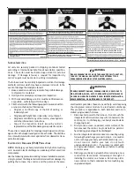
The vent/flue and combustion air pipes may terminate verti-
cally, as through a roof, or horizontally, as through an outside
wall.
Vertical pipe terminations should be as shown in the following
figure.
Refer to Vent/Flue Pipe and Combustion Pipe - Termina-
tion Locations
for details concerning location restrictions. The
penetrations through the roof must be sealed tight with proper
flashing such as is used with a plastic plumbing vent.
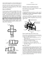
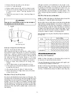
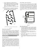
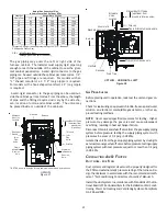
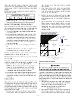
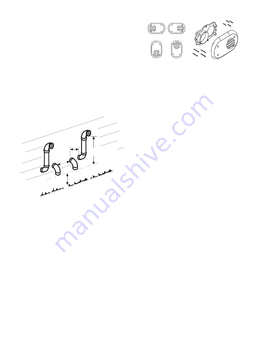
Vent & Combustion Air Intake Measurements for Standard
Horizontal Terminations (Dual Pipe)
Center to center = 10” min / 24” max.
Vertical separation: 0” - 24”
Vent termination from wall = 8” min / 12” max.
Combustion air intake from wall = 6” max.
Vent and intake clearance to ground or anticipated snow
level = 12” min.
3” MIN
12” MIN TO GRADE OR HIGHEST
ANTICIPATED SNOW LEVEL
3”MIN
24”MAX
12” MIN SEPARATION
Termination of Multiple Direct Vent Furnaces
Figure 18
V
ENT
/I
NTAKE
T
ERMINATIONS
F
OR
I
NSTALLATION
OF
M
ULTIPLE
D
IRECT
V
ENT
F
URNACES
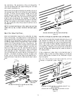
If more than one direct vent furnace is to be installed vertically
through a common roof top, maintain the same minimum clear-
ances between the exhaust vent and air intake terminations of
adjacent units as with the exhaust vent and air intake termina-
tions of a single unit.
If more than one direct vent furnace is to be installed horizon-
tally through a common side wall, maintain the clearances as in
the following figure. Always terminate all exhaust vent outlets at
the same elevation and always terminate all air intakes at the
same elevation.
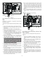
C
ONCENTRIC
V
ENT
T
ERMINATION
Refer to the directions provided with the Concentric Vent Kit
(DCVK) for installation specifications.
Ve rtica l Installa tion
H orizonta l Installation
Side Wall Vent Kit
Figure 19
S
IDE
W
ALL
V
ENT
K
IT
This kit is to be used with 2” or 3” direct vent systems. The
vent kit must terminate outside the structure and may be in-
stalled with the intake and exhaust pipes located side-by-side or
with one pipe above the other. These kits are
NOT
intended for
use with single pipe (non-direct vent) installations.
Refer to the directions furnished with the Side Wall Vent Kit
(p/n 0170K00000S or 0170K00001S) for installation speci-
fications.
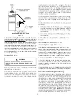
C
ONDENSATE
D
RAIN
L
INES
& D
RAIN
T
RAP
A condensing gas furnace achieves its high level of efficiency by
extracting heat from the products of combustion to the point
where condensation takes place. The condensate must be col-
lected in the furnace drain trap and routed to an appropriate
drain location in compliance with local and national codes.
Follow the bullets listed below when installing the drain system.
Refer to the following sections for specific details concerning
furnace drain trap installation and drain hose hook ups.
•
The drain trap supplied with the furnace must be
used.
•
The drain trap must be primed at time of
installation.
•
The drain line between furnace and drain location
must meet local and nation codes.
•
The drain line between furnace and drain location
must maintain a 1/4 inch per foot downward slope
toward the drain.
•
Do not trap the drain line in any other location than at
the drain trap supplied with the furnace.
•
If the drain line is routed through an area which may
see temperatures near or below freezing, precautions
must be taken to prevent condensate from freezing
within the drain line.


