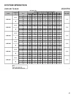


SERVICING
37
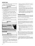
Orifices should be treated with care in order to prevent
damage. They should be removed and installed with a box-
end wrench in order to prevent distortion. In no instance
should an orifice be peened over and redrilled. This will
change the angle or deflection of the vacuum effect or
entraining of primary air, which will make it difficult to adjust
the flame properly. This same problem can occur if an orifice
spud of a different length is substituted.
WARNING
D
I
SCONNECT
ALL
G
AS AN
D
E
LECT
RI
CAL
P
O
W
E
R
S
U
PP
LY.
1. Check orifice visually for distortion and/or burrs.
2. Check orifice size with orifice sizing drills.
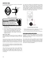
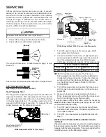
A
GAS
STREAM B
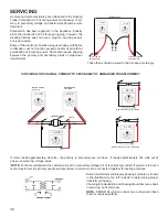
The length of Dimension “A” determines the angle of Gas
Stream “B”.
DENT OR
BURR
GAS
STREAM B
A dent or burr will cause a severe deflection of the gas stream.
S-307 Checking Gas Pressure
Gas Supply Pressure Measurement
Gas Pressure Test
The line pressure supplied to the gas valve must be within the
range specified below. The supply pressure can be measured
at the gas valve inlet pressure tap or at a hose fitting installed
in the gas piping drip leg. The supply pressure must be
measured with the burners operating. To measure the gas
supply pressure, use the following procedure.
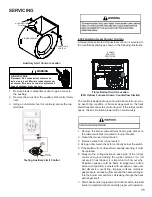
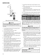
INLET
OUTLET
Gas Valve On/Off
Selector Switch
White-Rodgers Model 36J54 (Two-Stage)
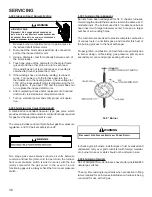
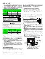
Manometer
Manometer
Hose
High Fire Regulator
Adjust
Regulator
Vent
On/Off Switch
High Fire Coil
Terminal (HI)
Coaxial Coil
Terminal (M)
Common
Terminal(C)
White-Rodgers Model 36J54 Connected to Manometer
3.5
White-Rodgers Model 36J54 Connected to Manometer
1. Turn OFF gas to furnace at the manual gas shutoff
valve external to the furnace.
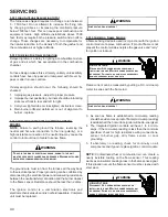
2. Connect a calibrated manometer (or appropriate gas
pressure gauge) at either the gas valve inlet pressure
tap or the gas piping drip leg. See White-Rodgers
36J54 gas valve figure for location of inlet pressure tap.
Natural Gas
Minimum: 4.5" w.c. Maximum: 10.0" w.c.
Propane Gas Minimum: 11.0" w.c. Maximum: 13.0" w.c.
INLET GAS SUPPLY PRESSURE
NOTE:
If measuring gas pressure at the drip leg, a
field-supplied hose barb fitting must be installed prior
to making the hose connection. If using the inlet pres-
sure tap on the White-Rodgers 36J54 gas valve, then
use the 36G/J Valve Pressure Check Kit, Part No.
0151K00000S.
3. Turn ON the gas supply and operate the furnace and
all other gas consuming appliances on the same gas
supply line.
4. Measure furnace gas supply pressure with burners
firing. Supply pressure must be within the range speci
-
fied in the
Inlet Gas Supply Pressure
table.
If supply pressure differs from table, make the necessary
adjustments to pressure regulator, gas piping size, etc., and/
or consult with local gas utility.
5. Turn OFF gas to furnace at the manual shutoff valve
and disconnect manometer. Reinstall plug before turn-
ing on gas to furnace.
6. Turn OFF any unnecessary gas appliances stated in
step 3.
Gas Manifold Pressure Measurement and Ad
-
justment
Only small variations in gas pressure should be made by adjusting
the gas valve pressure regulator. The manifold pressure must be
measured with the burners operating. To measure and adjust the
manifold pressure, use the following procedure.


