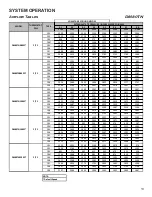
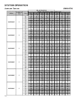
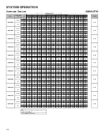
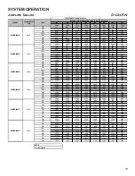
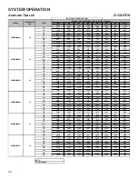
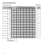
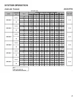
background image

SYSTEM OPERATION

21

Airflow Tables

DC80TN

0.1

0.2

0.3

0.4

0.5

0.6

0.7

0.8

CFM

CFM

CFM

CFM

CFM

CFM

CFM

CFM

F01

712

663

610

559

514

462

395

337

F02

1120

1081

1053

1022

990

955

918

887

F03

619

568

510

459

404

325

269

216

F04

825

784

741

694

650

609

563

520

F05

1000

963

930

893

852

816

776

745

F06

889

844

799

758

721

684

646

601

F07

1212

1198

1161

1138

1103

1076

1037

1007

F08

1362

1342

1307

1273

1252

1237

1211

1185

F09

1426

1405

1380

1359

1335

1312

1280

1254

F01

706

655

604

555

505

455

395

328

F02

1035

991

951

913

876

844

807

770

F03

630

572

521

466

411

341

269

216

F04

897

851

808

764

725

686

646

603

F05

1155

1113

1074

1039

1006

974

945

913

F06

1123

1077

1041

1006

973

941

907

875

F07

1255

1214

1181

1147

1116

1087

1056

1028

F08

1388

1331

1298

1266

1235

1207

1179

1151

F09

1421

1380

1348

1318

1289

1262

1233

1207

F01

868

811

752

692

631

510

452

399

F02

1157

1105

1058

1014

968

924

877

827

F03

738

672

598

510

413

360

309

N/A

F04

967

912

861

809

755

693

609

565

F05

1207

1158

1112

1065

1021

978

934

886

F06

1146

1111

1078

1041

1007

975

942

896

F07

1254

1213

1176

1137

1097

1054

1014

970

F08

1293

1264

1229

1199

1170

1138

1115

1074

F09

1394

1358

1322

1302

1267

1232

1196

1160

F01

1176

1105

1020

935

864

797

729

673

F02

1513

1459

1400

1335

1253

1182

1122

1067

F03

1022

813

674

585

511

431

334

282

F04

1640

1595

1540

1489

1436

1367

1307

1254

F05

1843

1786

1747

1690

1643

1575

1497

1435

F06

1580

1534

1495

1459

1429

1390

1356

1324

F07

1753

1713

1677

1642

1611

1576

1549

1518

F08

1523

1483

1438

1403

1370

1336

1299

1266

F09

1643

1599

1562

1525

1491

1462

1431

1394

F01

1176

1105

1020

935

864

797

729

673

F02

1513

1459

1400

1335

1253

1182

1122

1067

F03

1022

813

674

585

511

431

334

282

F04

1640

1595

1540

1489

1436

1367

1307

1254

F05

1843

1786

1747

1690

1643

1575

1497

1435

F06

1859

1819

1779

1734

1691

1641

1593

1520

F07

2028

1982

1946

1907

1861

1814

1749

1683

F08

2096

2045

2006

1974

1927

1882

1818

1765

F09

2203

2170

2138

2113

2074

2032

1990

1948

F01

1628

1571

1521

1472

1425

1380

1337

1291

F02

2159

2116

2072

2032

1992

1953

1916

1882

F03

956

777

675

587

468

377

324

296

F04

1561

1499

1441

1385

1336

1289

1243

1197

F05

2222

2174

2132

2090

2053

2013

1976

1944

F06

1833

1784

1735

1688

1645

1605

1562

1520

F07

1714

1659

1611

1564

1519

1473

1432

1387

F08

1926

1894

1849

1807

1764

1720

1683

1642

F09

1899

1853

1804

1761

1720

1681

1640

1602

DC80TN0403A*

G

DC80TN0603A*

G

CIRCULATION AIFLOW

MODEL

THERMOSTAT 

CALL

TAP #

EXTERNAL STATIC PRESSURE, (INCHES WATER COLUMN)

DC80TN0805C*

G

DC80TN1005C*

G

DC80TN0603B*

G

DC80TN0804B*

G

Summary of Contents for DM80TN

Page 1: ...ROPRIATE SERVICE MANUAL BEFORE BEGINNING REPAIRS Only personnel that have been trained to install adjust service or repair hereinafter service the equipment specified in this manual should service the...

Page 2: ...after servicing WARNING FIRE EXPLOSION OR CARBON MONOXIDE POISONING HAZARD Failure to replace with proper control could result in fire explosion or carbon monoxide poisoning This appliance uses NEGATI...

Page 3: ...ational Fuel Gas Code ANSI Z223 1 WARNING If not installed operated and maintained in accordance with the manufacturer s instructions this product could expose you to substances during fuel combustion...

Page 4: ...259 216 El mon xido de carbono puede causar enfermedades severas como da o cerebral permanente muerte Las emisiones de mon xido de carbono pueden circular a trav s del aparato cuando se opera en cualq...

Page 5: ...Initial Release B 1st Revision Configuration M Upflow Horizontal Major Revision C Downflow Horizontal A Initial Release B 1st Revision Nox AFUE 80 80 AFUE 92 92 AFUE 96 96 AFUE 97 97 AFUE Cabinet Widt...

Page 6: ...d in accordance with local codes or in their absence with the latest edition of The National Electric Code ANSI NFPA 70 and or The Canadian Electric Code CSA C22 1 An electrical disconnect must be pro...

Page 7: ...to high fire 1 Auto 2 Fixed Time Press the Left or Right menu switches to get to the A H S menu The menu will display these options no 10 20 30 60 AUt Fixed time options are expressed in minutes on t...

Page 8: ...ating mounting grounding and controlling these accessories Accessory wiring connections are to be made through the 1 4 quick connect terminals provided on the furnace integrated control module The hum...

Page 9: ...blower is energized When the thermostat is satisfied The gas valve is de energized The inducer remains energized for the post purge period 15 seconds The indoor blower runs for the selected off delay...

Page 10: ...r the thermostat is satisfied the compressor is de energized and the Cool Mode Fan Off Delay period begins Following the Cool Mode Fan Off Delay period the cool circulator and air cleaner relay are de...

Page 11: ...ACE BEFORE CHANGING SPEED TAPS WARNING CIRCULATING AIR AND FILTERS DUCTWORK AIR FLOW Duct systems and register sizes must be properly designed for the C F M and external static pressure rating of the...

Page 12: ...500 1459 1419 1387 1349 1317 1286 F01 1036 985 940 895 848 799 751 705 F02 1391 1352 1314 1278 1241 1209 1175 1140 F03 710 646 580 515 432 367 314 274 F04 1138 1091 1045 1001 959 920 876 832 F05 1209...

Page 13: ...156 1103 1037 982 932 878 F05 1811 1769 1730 1686 1649 1610 1572 1525 F06 1541 1487 1440 1395 1353 1310 1251 1203 F07 1587 1545 1494 1451 1409 1367 1316 1266 F08 1703 1659 1613 1579 1537 1495 1451 140...

Page 14: ...544 1500 1459 1419 1387 1349 1317 1286 F01 1036 985 940 895 848 799 751 705 F02 1391 1352 1314 1278 1241 1209 1175 1140 F03 710 646 580 515 432 367 314 274 F04 1138 1091 1045 1001 959 920 876 832 F05...

Page 15: ...07 1156 1103 1037 982 932 878 F05 1811 1769 1730 1686 1649 1610 1572 1525 F06 1541 1487 1440 1395 1353 1310 1251 1203 F07 1587 1545 1494 1451 1409 1367 1316 1266 F08 1703 1659 1613 1579 1537 1495 1451...

Page 16: ...19 1387 1349 1317 1286 F01 1036 985 940 895 848 799 751 705 F02 1391 1352 1314 1278 1241 1209 1175 1140 F03 710 646 580 515 432 367 314 274 F04 1138 1091 1045 1001 959 920 876 832 F05 1209 1166 1124 1...

Page 17: ...294 F04 1260 1207 1156 1103 1037 982 932 878 F05 1811 1769 1730 1686 1649 1610 1572 1525 F06 1541 1487 1440 1395 1353 1310 1251 1203 F07 1587 1545 1494 1451 1409 1367 1316 1266 F08 1703 1659 1613 1579...

Page 18: ...4 928 F05 1588 37 1539 39 1494 40 1447 41 1401 42 1358 1313 1267 F01 1420 29 1359 31 1301 32 1254 33 1206 34 1152 1100 1044 F03 826 N A 744 N A 661 N A 573 N A 485 N A 399 339 N A F04 1623 N A 1567 N...

Page 19: ...60 F01 1176 1105 1020 935 864 797 729 673 F02 1513 1459 1400 1335 1253 1182 1122 1067 F03 1022 813 674 585 511 431 334 282 F04 1640 1595 1540 1489 1436 1367 1307 1254 F05 1843 1786 1747 1690 1643 1575...

Page 20: ...96 1160 F01 1176 1105 1020 935 864 797 729 673 F02 1513 1459 1400 1335 1253 1182 1122 1067 F03 1022 813 674 585 511 431 334 282 F04 1640 1595 1540 1489 1436 1367 1307 1254 F05 1843 1786 1747 1690 1643...

Page 21: ...302 1267 1232 1196 1160 F01 1176 1105 1020 935 864 797 729 673 F02 1513 1459 1400 1335 1253 1182 1122 1067 F03 1022 813 674 585 511 431 334 282 F04 1640 1595 1540 1489 1436 1367 1307 1254 F05 1843 178...

Page 22: ...N A 636 N A F04 1309 32 1261 33 1218 34 F02 1393 43 1348 44 1308 45 F04 1309 45 1261 47 1218 49 F05 1459 41 1414 42 1371 43 F01 1176 35 1105 38 1020 41 F03 1022 N A 813 N A 674 N A F04 1640 N A 1595...

Page 23: ...N A 402 349 300 F04 1182 35 1142 36 1103 1064 1025 F02 1270 47 1230 48 1196 1158 1123 F04 1182 50 1142 52 1103 1064 1025 F05 1336 44 1297 46 1264 1229 1193 F01 935 44 864 48 797 729 673 F03 585 N A 5...

Page 24: ...in 7 Secs increments from 0 to 35 Secs Cool Off Delay Delay Seconds Default set at 65 Secs Adjustments can be made in 5 Secs increments from 0 to 120 Secs Blower Speed for 1st Stage Gas Heat Mode xx...

Page 25: ...SYSTEM OPERATION 25 2 Stage Status Codes Status Menu Idle Continous Fan Compressor Cooling Low Stage Compressor Cooling High Stage Gas heat Low Stage Gas heat High Stage OEM test Mode Mode Main Menu...

Page 26: ...CAL COMPONENTS ARE CONTAINED IN BOTH COMPARTMENTS TO AVOID ELECTRICAL SHOCK INJURY OR DEATH DO NOT REMOVE ANY INTERNAL COMPARTMENT COVERS OR ATTEMPT ANY ADJUSTMENT CONTACT A QUALIFIED SERVICE AGENT AT...

Page 27: ...2 164 327 655 1636 37 97 195 486 12 75 150 300 600 1500 38 23 47 95 189 474 13 69 138 277 555 1385 39 92 185 462 14 64 129 257 514 1286 40 22 45 90 180 450 15 60 120 240 480 1200 41 176 439 16 56 113...

Page 28: ...he gas valve turn downward clockwise to increase pressure and input and upward counterclockwise to decrease pressure and input A properly operating unit must have the BTU per hour input and CFM of air...

Page 29: ...king Auxiliary Limit Control 34 S 302 Checking Flame Rollout Control 35 S 303 Induced Draft Blower Motor 36 S 304 Checking Gas Valve Redundant 36 S 305 Checking Main Burners 36 S 306 Checking Orifices...

Page 30: ...tely 144 volts out of phase reverse low voltage wires NOTE For flame rectification the common side of the secondary voltage 24 V is cabinet grounded If you were to bench test a transformer the primary...

Page 31: ...king Thermostat And Wiring DISCONNECT ALL POWER BEFORE SERVICING WARNING 1 Remove the blower compartment door to gain access to the thermostat low voltage wires located at the furnace integrated contr...

Page 32: ...T1 T5 wires on the control board Green ground wire connected to cabinet ground The control harness has The nine speed ECM motor requires a line voltage power supply black connected to CIRC H and white...

Page 33: ...urnace as possible Thermometers must not be influenced by radiant heat by being able to see the heat exchanger SUPPLY AIR RETURN AIR Checking Temperature Rise 3 Subtract the return air temperature fro...

Page 34: ...sh ELEVEN times If the limit circuit opens and does not close within fifteen minutes the control assumes the manual rollout or fuse has opened and the RED LED will flash FIVE times The control will en...

Page 35: ...ut occur An over firing condition or flame impingement on the heat shield may also cause the control to open If the rollout control opens the air circulation blower will run continuously 1 Remove the...

Page 36: ...s used The valve provides control of main burner gas flow pressure regulation and 100 percent safety shut off Two stage gas valves always require 24 volts between common and low fire main coil to open...

Page 37: ...e Rodgers Model 36J54 Connected to Manometer 3 5 White Rodgers Model 36J54 Connected to Manometer 1 Turn OFF gas to furnace at the manual gas shutoff valve external to the furnace 2 Connect a calibrat...

Page 38: ...outlet pressure tap White Rodgers 36J54 valve Turn outlet pressure test screw in to seal pressure port clockwise 7 in lb mini mum 14 Turn on electrical power and gas supply to the system 15 Close the...

Page 39: ...r at the moment of ignition after a burner heats up or when the burner turns off The latter is known as extinction pop Since the end results of flashback and delayed ignition can be the same burning i...

Page 40: ...e electrical panel Proper grounding can be confirmed by disconnecting the electrical power and measuring resistance between the neutral white connection and the burner closest to the flame sensor Resi...

Page 41: ...t Correct short at flame sensor or in flame sensor wiring Short to ground in flame sense circuit Lingering burner flame Slow closing gas valve Open fuse Replace fuse Short in low voltage wiring Locate...

Page 42: ...ated control board Furnace fails to operate No 115 power to furnace or no 24 volt power to integrated control module Restore high voltage power to furnace and integrated control module Blown fuse or t...

Page 43: ...G OF AT LEAST 105 C USE COPPER CONDUCTORS ONLY 4 UNIT MUST BE PERMANENTLY GROUNDED AND CONFORM TO N E C AND LOCAL CODES 5 TO RECALL THE LAST 6 FAULTS MOST RECENT TO LEAST RECENT DEPRESS SWITCH FOR MOR...

Page 44: ...EEDBACK Daikin is very interested in all product comments Please fill out the feedback form on the following link https daikincomfort com contact us You can also scan the QR code on the right to be di...

Reviews: