SERVICING
46
2. Check orifice size with orifice sizing drills.
3. If resizing is required, a new orifice of the same physical
size and angle with proper drill size opening should be
installed.
S-307 CHECKING GAS PRESSURE
Gas inlet and manifold pressures should be checked and
adjusted in accordance to the type of fuel being consumed.
WARNING
Disconnect gas and electrical power supply.
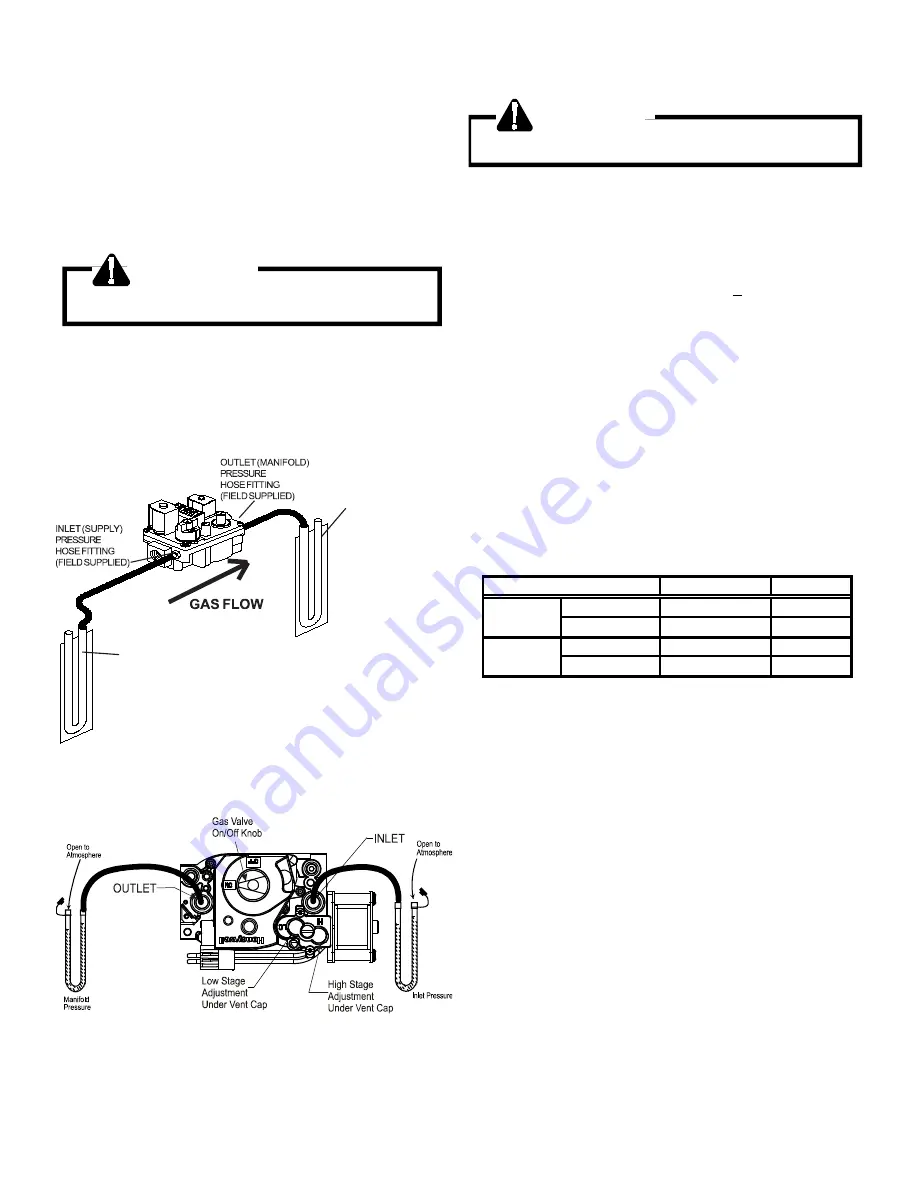
1. Connect a water manometer or adequate gauge to the
inlet pressure fitting of the gas valve.
2. Remove the pressure tap fitting at the manifold if provided
or check at the gas valve outlet fitting and connect another
manometer or gauge.
NOTE!
SUPPLY PRESSURE
IS TO BE BETWEEN 5.0 & 7.0 INCHES NATURAL
AND 11.0 & 14.0 INCHES L.P. WITH THE FURNACE
OPERATING.
INLET (SUPPLY) PRESSURE MANOMETER
(FIELD SUPPLIED)
OUTLET (MANIFOLD)
PRESSURE MANOMETER
(FIELD SUPPLIED)
MANIFOLD PRESSURE
IS TO BE BETWEEN
3.2 & 3.7 NATURAL AND
10.0 & 11.0 INCHES L.P.
HIGH FIRE OR
SINGLE STAGE AND
BETWEEN
1.7 AND 2.3 INCHES
NATURAL
7.0 & 8.0 INCHES
LOW STAGE
NOTE!
TWO-STAGE H VALVE
MEASURING INLET AND MANIFOLD GAS PRESSURE
HONEYWELL 2 STAGE GAS VALVE
With Power ON:
WARNING
Line Voltage now present.
3. Put unit into heating cycle and turn on all other gas con-
suming appliances.
For
NATURAL GAS:
a. Inlet pressure should be a nominal 7" w.c.
b. (2 stage heat models only) Manifold pressure on
low stage should be 2.0" w.c.
+
3" w.c.
c. Manifold pressure for single stage heat models and
2 stage heat models on high stage should be 3.5”
± .3"w.c.
For
PROPANE GAS:
a. Inlet pressure should be a nominal 11" w.c.
b. (2 stage heat modles only) Manifold pressure for 2
stage heating models on low stage should be 6"
w.c.
c. Manifold pressure for single stage heat models and
2 stage heat models on high stage should be 10”
w.c.
Range
Nominal
Low Stage
1.6 - 2.2" w.c.
2.0" w.c.
High Stage
3.2 - 3.8" w.c.
3.5" w.c.
Low Stage
5.7 - 6.3" w.c.
6.0" w.c.
High Stage
9.7 - 10.3" w.c.
10.0" w.c.
MANIFOLD GAS PRESSURE
Natural
Propane
Gas
2 Stage Heat Models
If operating pressures differ from chart, make necessary
pressure regulator adjustments, check piping size, etc., and/
or consult with local utility.
S-308 CHECKING FOR DELAYED IGNITION
Delayed ignition is a delay in lighting a combustible mixture of
gas and air which has accumulated in the combustion chamber.
When the mixture does ignite, it may explode and/or rollout
causing burning in the burner venturi.
If delayed ignition should occur, the following should be
checked:
1. Improper gas pressure - adjust to proper pressure. (See
S-307)
2. Improper burner positioning - burners should be in locating
slots, level front to rear and left to right.
3. Carry over (lighter tube or cross lighter) obstructed - clean.
4. Main burner orifice(s) deformed, or out of alignment to
burner - replace.
Summary of Contents for DBG Series
Page 51: ...51 ACCESSORIES GAS ELECTRIC...
Page 52: ...ACCESSORIES 52 GAS ELECTRIC...
Page 53: ...53 ACCESSORIES...
Page 54: ...ACCESSORIES 54...
Page 95: ...95 DBC COMMERCIAL 15 25 Ton Packaged Air Conditioner Unit WIRING DIAGRAMS...
Page 100: ...100 DBG COMMERCIAL 15 25 Ton Packaged Gas Electric Unit WIRING DIAGRAMS...


