D2CND0 D2CND0 D2TND0
D2TND0 D2TND024A4AA
Wall-mounted condensing boiler
ESIE17-09 / 2017.11
Servicing manual
40
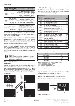
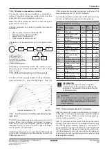
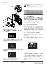
6. Pressing “Menu/Enter” within the next 5 minutes the pa
-
rameters from the BCC will be transferred to the PCB. During
the transfer the display circle shows a progress animation as
shown below:
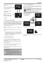
7. If the Parameter transfer finishes without an error the Dis
-
play shows “Fin”.
8. After “Fin“ the boiler restarts immediately like Power On and
it works with the new Parameters from the BCC.
After a BCC is installed to a PCB, that PCB does
not work without BCC. If BCC is missing, the
display will show error code UA-67.
NOTICE
After a BCC installation procedure the boiler has to
be checked for all safety-relevant behaviors like it
has to be done during the installation of the boiler.
WARNING
9.1.3
Plugging wrong BCC
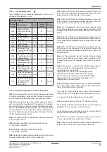
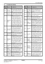
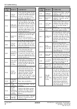
If an inappropriate BCC is plugged to a PCB the Display
shows one of the error codes UA-68 or UA-69. These errors
are Lockout errors which are not resettable. The boiler has to
be switched off and BCC must be replaced with the correct
one. After correct BCC is plugged and update procedure fin
-
ished, former UA-68 (or UA69) error code will still be shown
on display. Resetting the boiler will remove the error.
9.1.4
Error during Parameter-transfer
If an error occurs during the Parameter-transfer or if parameter
update is not initiated within 5 minutes, the display shows er
-
ror code UA-70.This is a Lockout error. BCC installation steps
described in “BCC installation procedure” must be repeated.
After BCC installation procedure finished, former UA-70 error
code will still be shown on display. Resetting the boiler will
remove the error.
9.1.5
Re-installing an already installed BCC
If there is a need to re-install the parameters from the installed
BCC to the PCB (returning factory-settings), please follow the
sequence below:
1. Switch off the boiler, wait a few seconds and switch on the
boiler again.
2. Within the first seconds after Power On the Display-Test is
in progress.
3. During this Display-Test, press ‘Cancel/Back’ and ‘Menu/
Enter’ buttons simultaneously for about 2 seconds to activate
the re-installation.
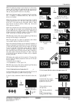
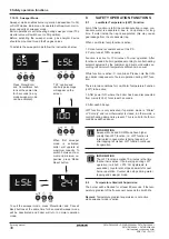
4. The Display then shows ‘reU’ (Re-Update) for a short time.
5. Next, the display changes to ‘oFF’ which indicates that a
power off and power on is necessary. Make power off and
power on.
6. Apply the steps described described in “BCC installation
procedure”.
9 Optional Parts
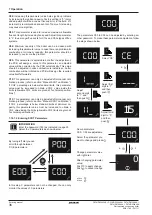
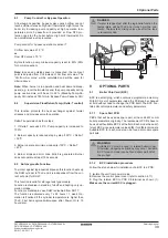
4. Connect the unit to main power supply.
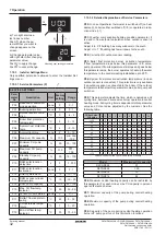
5. If the BCC firmware and ID are suitable to the PCB, the
display shows ‘bcc’:
(1)

