background image

BRBRC3E52C7

Wired remote controller

4P368040-1 – 2014.02

Quick reference

8

1

indoor unit

2

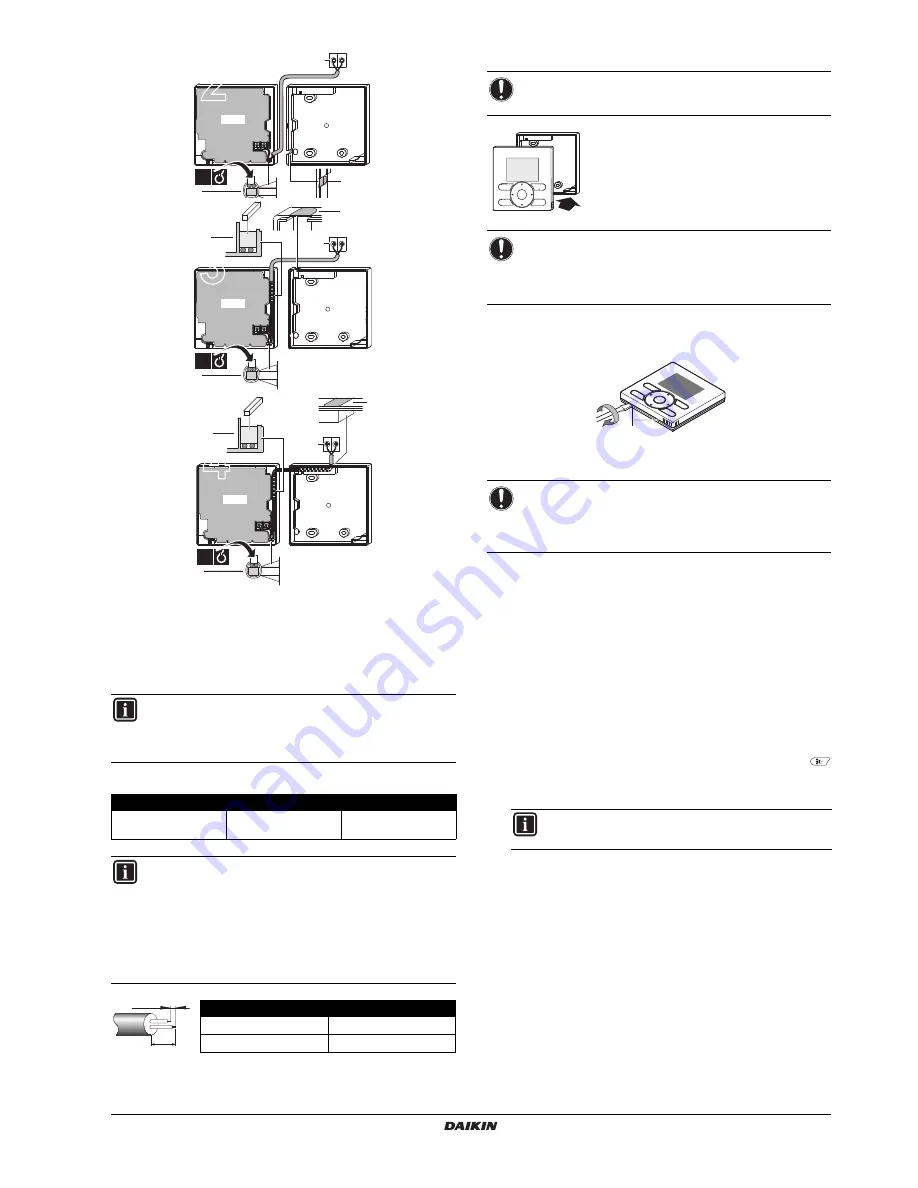
notch the part for the wiring to pass through with nippers, 
etc.

3

secure the wiring to the upper case using the wiring 
retainer and clamp.

Connect the terminals on the remote controller (P1, P2), and the
terminals of the indoor unit (P1, P2). (P1 and P2 do not have polarity.)

Wiring specifications

5. Attach the upper case

Align the upper case with the tabs of the lower
case (6 points) and insert the upper case.

First begin fitting from the clips at the bottom.

6. Remove the upper case

Insert a slot screwdriver into the slots in the lower case (2 places), to
remove the upper case.

7. Power on

1

Put on the power.

2

Checking the connection

Please stand by

. is displayed.

3

After a few seconds, the basic screen is displayed.

When controlling 1 indoor unit or 1 group of indoor units with 2
remote controllers

1

Put on the power for both remote controllers.

2

Determine which one is the sub and wich one is the main remote
controller.

3

When 

Error code: U5

 - 

Checking the connection

Please stand by

. is

displayed on both remote controllers, push and hold the 
button of the remote controller to be set as sub for 4 seconds.

4

The sub remote controller now displays 

Sub RC

.

5

After a few seconds, the basic screen is displayed.

INFORMATION

When wiring, run the wiring away from the power supply
wiring in order to avoid receiving electric noise (external
noise).

Wiring type

Size

Total length

Sheathed vinyl cord or 

cable

0.75–1.25 mm

2

500 m

INFORMATION

1

Peel the sheath for the part that has to pass through
the inside of the remote controller case (L). Refer to
the figure and the table below. It is important to keep
double isolation up through the notch of the remote
controller case.

2

For easy wiring, it’s better to keep ±10 mm difference
between the length of the 2 wires.

Wiring outlet

L

Top outlet

±150 mm

Top center outlet

±200 mm

1

2

P1 P2

PCB

2

3

P1 P2

1

2

3

PCB

3

3

1

2

P1 P2

PCB

4

3

3

10 mm

L

NOTICE

Be careful not to pinch the wiring when attaching.

NOTICE

1

The switchbox and connection wiring are not
included.

2

Do not directly touch the PCB with your hand.

NOTICE

The remote controller PCB is mounted on the upper case.
Be careful not to damage the PCB with the slot
screwdriver.

INFORMATION

The main remote controller still displays 

Main RC

.

1

Summary of Contents for BRC2E52C7

Page 1: ...QUICK REFERENCE BRC2E52C7 BRC3E52C7 Wired remote controller...

Page 2: ...REMOTE CONTROLLER The basic remote controller functions are ON OFF operation mode change over only for BRC2E temperature adjustment fan speed adjustment airflow direction adjustment 2 CLOCK FUNCTION...

Page 3: ...ir conditioner 7 OPERATION LAMP Lights up during operation This lamp is not lit when the unit operation is OFF Blinks if an error occurs 8 CANCEL BUTTON Used to return to the previous screen This butt...

Page 4: ...activated as required by the setpoint or setback operation 5 HEATING OPERATION In this mode heating will be activated as required by the setpoint or setback operation 6 VENTILATION HRV only The ventil...

Page 5: ...Set the time when the filter needs to be automatically cleaned This function is only available on models with the self cleaning decoration panel 8 MAINTENANCE INFORMATION Display the service contact...

Page 6: ...Display the Settings screen refer to Appendix on page 10 2 Use to select the desired day 1 3 Use to highlight the Operation start Time and to set the desired Operation start Time 2 4 Use to highlight...

Page 7: ...to Appendix on page 10 2 Use to move the highlighted item and to set Year Month Day and time 3 Push to display the confirmation screen 4 Use to select Yes and push To set the hour format 12 24 hours...

Page 8: ...e top center WARNING Carefully read these instructions before installation They will tell you how to install how to configure and how to use the unit properly Keep this manual in a handy place for fut...

Page 9: ...e stand by is displayed on both remote controllers push and hold the button of the remote controller to be set as sub for 4 seconds 4 The sub remote controller now displays Sub RC 5 After a few second...

Page 10: ...nd Dual Setpoint mode Software update with Updater Maintenance 1 General safety precautions Wipe the LCD display and the rest of the surface of the remote controller with a dry cloth when they become...

Page 11: ...Individual Setting List Reset All Indivi Setting Airflow Direction Range Ventilation Ventilation Rate Ventilation Mode 9 11 12 13 14 15 16 17 18 19 Energy Saving Options Energy Saving List Setpoint R...

Page 12: ...4P368040 1 2014 02 Copyright 2014 Daikin...

Reviews: