DAIKIN
3P665364-9
U M22P1 00B
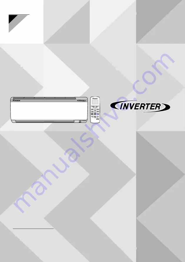
DAIKIN ROOM AIR CONDITIONER
OPERATION MANUAL
MODELS: A/D/F/G/MTKL50UV16V3
F/GTKY35UV16W3
F/G/MTKM50UV16V3
A/D/F/G/MTKL35UV16W3
Page 1: ...DAIKIN 3P665364 9U M22P1 00B DAIKIN ROOM AIR CONDITIONER OPERATION MANUAL MODELS A D F G MTKL50UV16V3 F GTKY35UV16W3 F G MTKM50UV16V3 A D F G MTKL35UV16W3 3P665364 9U M22P1 00B...
Page 2: ...uality and or longevity of the object concerned Do not expose plants or animals directly to the airflow from the unit as this may cause adverse effects Do not place appliances that producenaked flames...
Page 3: ...er Receives signals from the remote controller When the unit receives a signal you will hear a beep sound Case Sound type Operation start beep beep Settings changed beep Operation stop long beep 13 In...
Page 4: ...OFF TIMER button 14 GOOD SLEEP DISPLAY button 15 DEW CLEAN button NOTE Notes on remote controller 7 9 10 14 13 S NO 1 2 7 4 Never expose the remote controller to direct sunlight DAIKIN 011 I I POWER L...
Page 5: ...ontroller Do not get it wet The maximum transmission distance is about 7m To attach the accessory filters i Receiver Set the accessory filters under the tabs of the filter Ac esso yfUte i n h 0 Y u f...
Page 6: ...the accessory filter and the decomposition power of the streamer discharge combine to reduce unpleasant odours and viruses cleaning the air in the room To start operation 1 Press I c I STREAMER When l...
Page 7: ...LD LOCK disables all the buttons except when ECONO and POWERFULL button press together for about 5 seconds To set the CHILD LOCK Press and o_WE_R_c 1L together for about 5 seconds e will be displayed...
Page 8: ...ades will begin to swing The 3 D airflow direction 1 Press 1SWIN and SWING and e are displayed on the LCD The flap and louvres move in turn To cancel 3 D airflow press either 4swiNaj or sw1NG again Th...
Page 9: ...uses the settings to be cancelled and disappears from the LCD ECONO operation functions in COOL and DRY operation POWER CHILL and ECONO operation cannot be used at the same time is displayed on the LC...
Page 10: ...time default 2HR are displayed on the LCD IC O ON OFF c J The TIMER lamp lights Display orange TEMP 2 Press v while C is blinking Each pressing of the button changes tempera ture shift value by 1 c Yo...
Page 11: ...t temperature does not display when the unit is in DRY operation or FAN operation Inverter output and set temperature may not display depending on the operation mode that is active The display turns o...
Page 12: ...Dry mode OFF Cooling operation To cancel DEW CLEAN operation Turn OFF the machine from Remote Controller Wi Fi Control NOTE Note on LED 7 Segment Brightness Control Ld indicates for the brightness Li...
Page 13: ...age the front panel shaft on the other side in the same manner After disengaging both front panel shafts pull the front panel toward yourself and remove it 3 Clean the front panel Wipe it with a soft...
Page 14: ...with a vacuum cleaner If the dust does not come off easily wash them with neutral detergent thinned with lukewarm water then let them dry in the shade Be sure to remove the accessory filter optional p...
Page 15: ...m Titanium apatite deodorizing air purifying filter 1 set Ag ion filter 1 set Anti Microbial filter 1 set Micro filter PM2 5 1 set Micro filter PM2 5 for streamer unit 1 set Micro filter PM 1 0 for st...
Page 16: ...es operation in about 3 minutes Voltage range protection 130V 285V Voltage range protection 130V 265V for F GTKL71UV16T Models A sound is heard A sound like flowing water This sound is generated becau...
Page 17: ...been tripped or the fuse blown operate Is there a power failure OPERATION lamp is off Are batteries set in the remote controller Is the timer setting correct The room does not cool down Is the airflo...
Page 18: ...air conditioner automatically resumes operation in about 3 minutes You should just wait for a while If there is a risk lightning could strike in the neighbourhood stop operation and turn off the circu...
Page 19: ...TART UP E7 DC FAN MOTOR FAULT E8 OVERCURRENT INPUT F3 HIGH TEMPERATURE DISCHARGE PIPE CONTROL F6 HIGH PRESSURE CONTROL IN COOLING F8 OPERATION HALT DUE TO COMPRESSOR INTERNAL TEMPERATURE ABNORMALITY O...
Page 20: ......
Page 21: ...re installed securely Fall vibration noise No refrigerant gas leaks Incomplete cooling function Refrigerant gas and liquid pipes and indoor drain hose Water leakage extension are thermally insulated D...
Page 22: ...as stopvalve sservice port thenfullyopenliquidandgas stop valves Do not attempt to turn valve rod beyond its stop 8 Tighten valve caps and service port caps for the liquid and gas stop valves with a t...
Page 23: ...ue 32 7 39 9N m 21 6 27 4N m O D 9 5mm 333 407 kgf cm 220 280 kgf cm Gas side I 0 D 12 7mm 49 5 60 3N m 48 1 59 7N m 505 615 kgf cm O D 15 9mm 61 8 75 4N m 490 61O kgf cm 10 8 14 7N m 110 150 kgf cm 6...
Page 24: ...cause condensation or water dripping f Heat insulationpipe cover Slit llll lfflll Slit Vinyl tape This illustration shows the case of the left rear piping Sectional view wire Insulation tape Drain hos...
Page 25: ...hthe unit WARNING ____________________________________1_a_b1e_N_o_ 6 Use a stabiliser if required by the voltage supply condition Do not use tapped wires extension cords or starburst connections as th...
Page 26: ...indoor unit to the A mounting plate with the E indoor unit fixing screws M4 x 12L 10 Caulk thegap between the pipeand the front grille with putty 11 After completing refrigerant piping wiring and drai...
Page 27: ...id pipeend Gaspipeend Drainhose position Applicable Unit Size Type H X W X D A B C i 298 X 800 X 229 800 116 5 116 5 298 X 821 X 235 821 128 126 5 298 X 885 X 229 885 116 5 116 5 298 X 906 X 235 906 1...
Page 28: ...you 2 Pun1 _ _r p Installation method 1 Install the front grille and firmly engage the upper hooks 3 locations 2 Install 3 screws of the front grille 3 Install the air filter and then mount the front...
Page 29: ...e length is 3m in order to avoid noise from the outdoor unit and vibration Mechanical noise and vibration may occur depending on how the unit is installed and the environment in which it is used Dimen...
Page 30: ...t the unit may cause interference with the picture or sound 9 the unit can be installed at the recommended height 1 8m 10 no laundry equipment is nearby fflGi l li11 114 The outdoor unit should be pos...
Page 31: ...rant gas leaks during installation ventilate the area immediately 0 Toxic gas may be produced if the refrigerant comes into contact with fire After completing installation check for refrigerant gas le...
Page 32: ...3P665364 9U M22P101B DAIKIN ROOM AIR CONDITIONER INSTALLATION MANUAL l MODELS A D F G MTKL50UV16V3 F GTKV35UV16W3 F G MTKM50UV16V3 A D F G MTKL35UV16W3 J C JNVERTER 3P665364 9U M22P101B...