


8
■
English
Outdoor Unit Installation
1.
Installing the outdoor unit
1) When installing the outdoor unit, refer to “
Precautions for Selecting a Location
” on page 3 and the “
Outdoor Unit
Installation Diagram
” on page 4.
2) If drain work is necessary, follow the procedures below.
2.
Drain work
CAUTION
In cold areas, do not use a drain socket, drain caps (1,2)
and a drain hose with the outdoor unit. (Drain water may
freeze, impairing heating performance.)
• If the drain port is covered by a mounting base or floor
surface, place additional foot bases of at least 1-1/4
inch (30mm) in height under the outdoor unit’s feet.
1) Attach
C
drain cap (1) and
D
drain cap (2).
2) Attach
B
drain socket.
•
When attaching
B
drain socket to the bottom
frame, make sure to connect the drain hose to the
drain socket first.
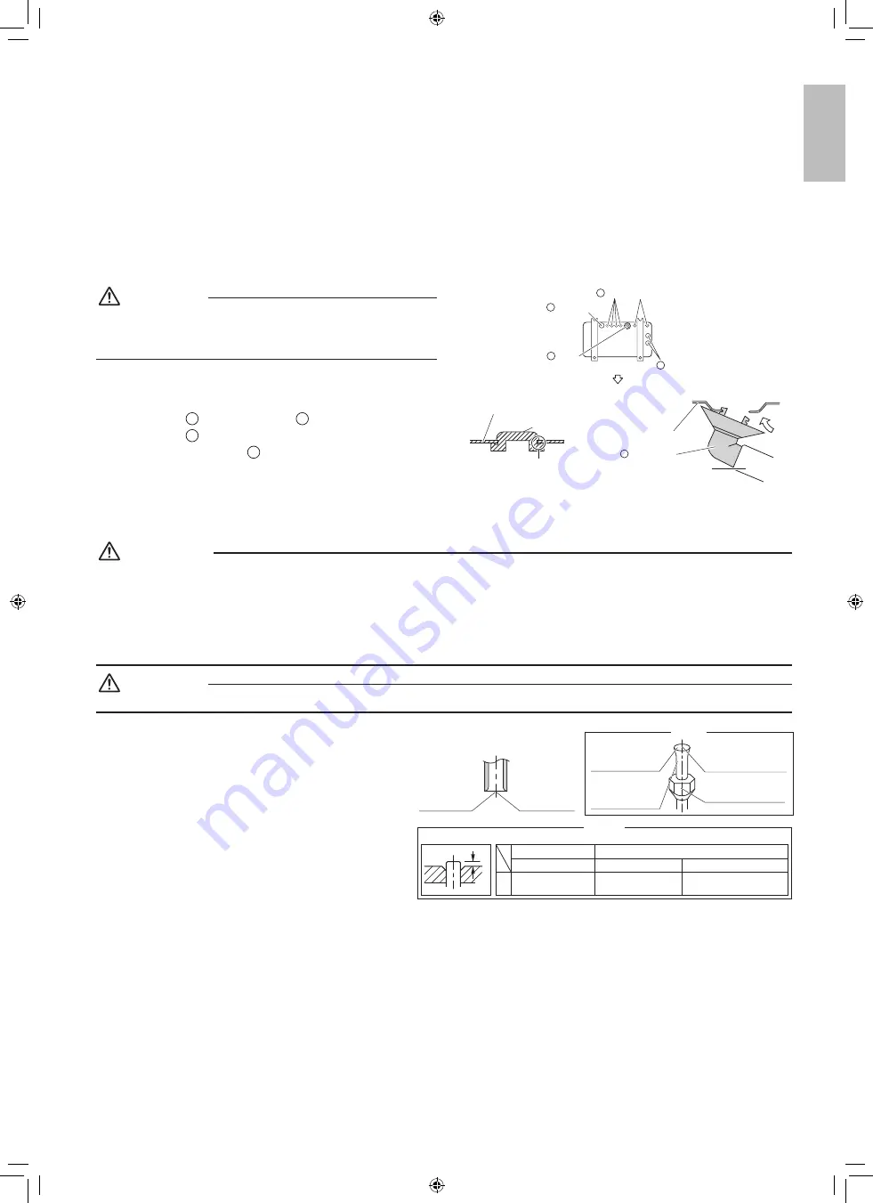
3.
Flaring the pipe end
WARNING
• Do not apply mineral oil to the flare.
•
Prevent mineral oil from getting into the system as this would reduce the service life of the units.
•
Never use piping which has been used for previous installations. Only use parts which are delivered with this unit.
•
Never install a dryer to this R410A unit in order to guarantee its service life.
•
The drying material may dissolve and damage the system.
• Improper flaring may result in refrigerant gas leakage.
CAUTION
Do not reuse joints which have been used once already.
1) Cut the pipe end with a pipe cutter.
2) Remove burrs with the cut surface facing
downward, so that the filings do not enter the
pipe.
3)
Put the flare nut on the pipe.
4) Flare the pipe.
5)
Check that the flaring has been done correctly.
Check
The flare
’
s inner
surface must be
flaw-free.
When flaring, do
not over-tighten
and crack.
The pipe end must be
evenly flared in a
perfect circle.
Make sure that
the flare nut is fitted.
Set exactly at the position shown below.
Flaring
A
Die
A
0-0.020 inch
(0-0.5mm)
Clutch-type
Flare tool for R410A
0.039-0.059 inch
(1.0-1.5mm)
Clutch-type (Rigid-type)
0.059-0.079 inch
(1.5-2.0mm)
Wing-nut type (Imperial-type)
Conventional flare tool
Cut exactly at
right angles.
Remove burrs.
Bottom frame
Drain cap
Pinch the bottom
frame in.
Drain cap (1)
Drain cap (2)
D
Drain cap (2)
Air outlet side
B
Drain
socket
C
D
Bottom frame
Drain socket
Hose (available commercially,
inner dia. 5/8 ” (16mm))
B
English
01_EN_3P675080-1.indd 8
3/24/2022 16:01:43


