background image

SFLC-212-173 


№ 

Setting item 

3-phase 3-wire 

Single-phase 

3-wire 

(U-N-W) 

Single-phase 

110V input 

220V input 

110V input 

220V input 

Display 
combination 

Pattern 

Pattern 1 

Pattern 1 

Pattern 1 

Main monitor 

A(V) 

A(U) 

Sub monitor (Left) 

V(UV) 

V(UN) 

Sub monitor (Center) 

Sub monitor (Right) 

Wh 

Wh 

Wh 

Bar graph 

A(V) 

A(U) 

Alarm output 
(

Factor 

DA 

DA 

DA 

Reset form 

AUTO  

AUTO  

AUTO  

Contact delay time 

0 second  

0 second  

0 second  

Demand 
detection 

Demand 
current 

Upper limit <H> 

80.0A 

400.0A 

40.00A 

Interval  

0 second  

0 second  

0 second  

Demand 
power 

Upper limit <H> 

OFF 

OFF 

OFF 

Interval  

0 second  

0 second  

0 second  

Operation form  

Operating system 
according with bimetallic 
type. 

Operating system 
according with 
bimetallic type. 

Operating system 
according with bimetallic 
type. 

Instant 
measurement 
detection  

Voltage upper limit 

OFF 

OFF 

OFF 

Voltage lower limit 

OFF 

OFF 

OFF 

5  Backlight  

Action 

AUTO 

AUTO 

AUTO 

Brightness (

3(Middle) 

3(Middle) 

3(Middle) 

Measurement 
range  

Voltage range  

6600V 

220.0V 

110.0V 

3300V 

220.0V 

Digit number of voltage range  4 digits 

4 digits 

4 digits 

4 digits 

4 digits 

Current range 

100.0A 

500.0A 

50.00A 

Current display intrinsic 
sensitivity 

100.0A 

500.0A 

50.00A 

Digit number of current range  4 digits 

4 digits 

4 digits 

Active power polarity 

One-way deflection 

One-way 
deflection 

One-way deflection 

Active power range 

1200kW 
( /1kW) 

40.00kW 
( /2kW) 

100.0kW ( /1kW) 

150.0kW 
( /500W) 

10.00kW 
( /1kW) 

Digit number of active power 
range 

4 digits 

4 digits 

4 digits 

4 digits 

4 digits 

Reactive power range 

LEAD 600.0  
to 0.0 to  
LAG 600.0kvar 
( /500var) 

LEAD 20.00  
to 0.00 to  
LAG 20.00kvar 
( /1kvar) 

LEAD 50.00 to 0.00 
to LAG 50.00kvar 
( /500var) 

LEAD 75.00  
to 0.00 to  
LAG 75.00kvar 
( /250var) 

LEAD 5000  
to 0 to  
LAG 5000var 
( /500var) 

Digit number of reactive  
power range 

4 digits 

4 digits 

4 digits 

4 digits 

4 digits 

Power-factor range 

LEAD0.500 to 1.000 to 

LAG0.500 

LEAD0.500 to  
1.000 to LAG0.500 

LEAD0.500 to 1.000 

 to LAG0.500 

Frequency range 

45.0 to 65.0Hz 

45.0 to 65.0Hz 

45.0 to 65.0Hz 

Digit number of frequency range  3 digits 

3 digits 

3 digits 

Analog 
output 
(

Output factor 1 

A(V) 

A(U) 

Output factor 2 

V(UV) 

V(UN) 

Output factor 3 

Output 
intrinsic 
sensitivity 

Current 

100.0% 

100.0% 

100.0% 

Active power 

100.0% 

100.0% 

100.0% 

Reactive power 

50.0% 

50.0% 

50.0% 

Low input cut  

OFF 

OFF 

OFF 

Pulse output 
(

Factor  

Wh 

Wh 

Wh 

Pulse unit  

10kWh/pulse 

0.1kWh/pulse  1kWh/pulse 

1kWh/pulse 

0.1kWh/pulse 

9  External operation input (

Alarm reset 

Alarm reset 

Alarm reset 

Summary of Contents for SFLC-110L

Page 1: ...SFLC 212 173 INSTRUCTION MANUAL POWER LINE MULTI METER SFLC 110L 1 2W 1 3W 3 3W ANALOG OUTPUT HARDWARE MODEL F...

Page 2: ...Please securely tighten the terminal screws Please make sure that forgotten tightening of the terminal screw is not Preparation before use At the case of connect this product to the main power supply...

Page 3: ...nput within 1 second after switching on a power supply The maximum value a minimum value measurement factor Measurement factor Maximum value measurement Minimum value measurement Voltage Current Deman...

Page 4: ...Current display intrinsic sensitivity 100 0A 500 0A 50 00A Digit number of current range 4 digits 4 digits 4 digits Active power polarity One way deflection One way deflection One way deflection Acti...

Page 5: ...utput adjustment Output 1 Bias adjustment 0 0 0 0 0 0 Span adjustment 100 0 100 0 100 0 Output 2 Bias adjustment 0 0 0 0 0 0 Span adjustment 100 0 100 0 100 0 Output 3 Bias adjustment 0 0 0 0 0 0 Span...

Page 6: ...13 4 2 3 Setting display 15 4 3 Operation 16 4 3 1 The main monitor display element change 16 4 3 2 Phase line display change 16 4 3 3 Enlarged display of integral power consumption 17 4 3 4 Setting v...

Page 7: ...m value and an alarm output and the maximum minimum value is possible at setting Power supply is AC85 to 264V DC80 to 143V for both AC and DC uses The mounting method of this unit is compatible with t...

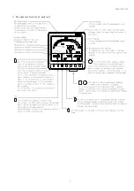
Page 8: ...change to setting mode In setting mode it is used as a switch that determines a set point RESET SHIFT Scale markings It sets automatically by measurement range setting Unit display It sets automatica...

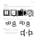
Page 9: ...agram Caution on handling Mount the LCD to obtain an optimum angle since the contrast changes according to the monitoring angle 1 For upper case installation 2 For lower case installation Installation...

Page 10: ...nd the ground to be lower than 100 4 Keep a distance of more than 30cm between this unit and the circuit breaker as well as between this unit and the relay contact signal line 5 No protection is neces...

Page 11: ...display of current voltage is changed It is used in case it terminates setting mode And it is used in case it returns the display combination of a measurement factor Convenient functions 1 In case a m...

Page 12: ...e Push 3 seconds or No operation 10 minute TEST mode Push 3 seconds Wh varh factor display A DA MDA V factor display At 1 2W With no function Alarm reset Output and display Conditions At manual reset...

Page 13: ...m value and the minimum value by switch operation These maximum values and the minimum value are reset by switch operation it updates to the instantaneous value at the time In addition as for the maxi...

Page 14: ...ue setting is a possible measurement factor demand current and demand power etc it displays in case an input exceeds a set point Besides the usual measurement display the detected factor is displayed...

Page 15: ...rm output hold in case setting as an alarm output of applicable factor The return in this case needs alarm reset operation Please refer to 4 3 7 Reset about alarm reset Alarm factor Example of a displ...

Page 16: ...No 111 Display pattern Setting mode 2 Setting of measurement range analog output pulse output and measurement display ON OFF is mainly performed And initialization of a setting value and reset of wat...

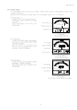
Page 17: ...A V Main monitor A W Initial display 4 3 2 Phase line display change Three phase three wire Single phase three wire A phase line display of current or voltage is changed Everything which is being indi...

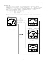
Page 18: ...output set point are checked Check is RESET SHIFT and are pushed simultaneously and performed The change of a set point is carries out by and DISPLAY is pushed in case it returns to the original measu...

Page 19: ...mode 1 Press SET for longer than 3 seconds Setting mode 2 Press SET and RESET SHIFT together for longer than 3 seconds Setting mode 3 Press SET and DISPLAY together for longer than 3 seconds Reference...

Page 20: ...ion in the setting mode 2 please refer to 5 3 2 Setting mode 2 Press SET and RESET SHIFT together for longer than 3 seconds It goes into the setting mode 2 MODE is pushed until setting is set to No 26...

Page 21: ...reset Reset of the various measurement values of maximum value and minimum value is performed This reset has two types of methods How to perform according to a measurement factor individual How to re...

Page 22: ...nues pushing RESET SHIFT and 1 second or more simultaneously Maximum Minimum measurement display Reset completion 4 Alarm reset and all reset of maximum value and minimum value It resets an alarm in a...

Page 23: ...38 123AL Alarm contact delay time Sets the contact delay time of alarm 0 second 38 131H Demand current upper limit Sets the high alarm value of demand current 80 Full scale 100 39 132 Demand current t...

Page 24: ...ange Sets the full scale of reactive power meter 3 3W 600 0kvar 11 42 45 1 3W 50 00kvar 1 2W 75 00kvar 12 21A Digit number of reactive power range Sets the digit number of reactive power range 3 3W 4...

Page 25: ...easurement display ON 48 254 Active power ON OFF Sets the ON OFF of active power measurement display ON 48 255 Demand power ON OFF Sets the ON OFF of demand power measurement display ON 48 256 Reactiv...

Page 26: ...wer transmission power receiving in measurement of reactive power and power factor General measurement 51 331 15 AO1 BIAS adjustment Sets the BIAS value of AO1 analog output 1 0 0 52 332 15 AO1 SPAN a...

Page 27: ...ent range of ammeter 213 Press SET and RESET SHIFT together for longer than 3 seconds 211 Press RESET SHIFT Press RESET SHIFT Select a measuring range by and 212 213 Press SET Selected measuring range...

Page 28: ...entered Press DISPLAY Returns to display mode 47 Sets the time interval of demand current 132 Press SET for longer than 3 seconds Press MODE Press MODE 111 121AL 131H Press RESET SHIFT Select an time...

Page 29: ...ET SHIFT 111 112 Press RESET SHIFT Press RESET SHIFT 113 114 115 Select an display factor by and Press SET Selected display factor is entered Press DISPLAY Returns to display mode 34 38 Sets the displ...

Page 30: ...elected output pulse unit is entered Press DISPLAY Returns to display mode 47 6 Setting of power factor and frequency measurement range Each parenthesized number shows a setting number and this number...

Page 31: ...display mode 42 45 Sets the digit number of current range 215 Press SET and RESET SHIFT together for longer than 3 seconds 211 Press RESET SHIFT Press RESET SHIFT Press RESET SHIFT 212 213 214 Press...

Page 32: ...o display mode 46 Sets the analog output sensitivity of a rated input power value to an output upper limit of active power 225A Press SET and RESET SHIFT together for longer than 3 seconds Press MODE...

Page 33: ...ger than 3 seconds Press MODE Press MODE 111 121AL 131H Select a high alarm value by and Press SET Selected high alarm value is entered Press DISPLAY Returns to display mode 39 Sets the high alarm val...

Page 34: ...mber shows a setting number and this number is displayed on the setting screen Items Setting and operation procedures Page Sets the tidal current measurement of reactive power and power factor 321 Pre...

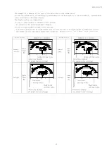
Page 35: ...Main monitor V UV V VW V WU A U A V A W DA U DA V DA W MDA U MDA V MDA W W DW MDW var cos Hz Wh Wh varh LAG varh LEAD varh LAG varh LEAD Sub monitor Left V UV V VW V WU A U A V A W W var cos Sub monit...

Page 36: ...AG varh LEAD varh LAG varh LEAD Sub monitor Left V UN V WN V UW A U A W A N W var cos Sub monitor Center V UN V WN V UW A U A W A N DA U DA W DA N MDA U MDA W MDA N W DW MDW var varh LAG varh LEAD var...

Page 37: ...Pattern 11 A cos W Wh A 12 Pattern 12 A var W Wh A 13 Pattern 13 W cos var Wh W 14 Pattern 14 A Wh A 15 Pattern 15 V Hz V Displays set factor Single phase 2 wire Main monitor V A DA MDA W DW MDW var c...

Page 38: ...WU 3 A U 4 A V 5 A W 6 W 7 var 8 cos 9 Nothing 0 DW 14 var 16 varh LAG 17 varh LEAD 18 varh LAG 19 varh LEAD 20 Nothing 0 V UV 1 V VW 2 V WU 3 A U 4 A V 5 A W 6 A V 5 A W 6 V UV 1 V VW 2 V WU 3 Wh 18...

Page 39: ...N RESET SHIFT MAX MIN RESET SHIFT MAX MIN 121AL Alarm output factor setting Sets the factor of alarms outputs Selection by and set value is updated by SET Default setting 1 DA Demand current OFF Nothi...

Page 40: ...operating system of demand DW can be selected from d operating system according with bimetallic type demand and A averaging arithmetic in demand time delay average Selection by and set value is updat...

Page 41: ...SET SHIFT MAX MIN 152 Backlight brightness 151 Backlight action It can select from ON always on AUTO auto off and OFF always off about action of backlight If 5 minutes elapses without operating a swit...

Page 42: ...en mistaken a display and output of measurement are not obtained correctly Therefore users must not set The setting item without the corresponding option is not displayed Setting mode 2 Display mode S...

Page 43: ...ive power and reactive power automatically simultaneously Selection by and set value is updated by SET Default setting 6600V 3 3W 110V input 110 0V 1 3W 3300V 1 2W 110V input 220 0V 3 3W 1 2W 220V inp...

Page 44: ...range can be selected within the limits of 40 to 120A Therefore a left table A measurement range can be selected from 40 42 45 48 50 56 60 64 72 75 80 84 90 96 100 120A 1 1 0 1 2 1 4 1 5 1 6 1 8 2 2...

Page 45: ...range Selection by and set value is updated by SET Default setting 4 digits The unit may be changed if the number of digits is changed Example 1200kW 1 20MW 219 Reactive power range Sets the full scal...

Page 46: ...ange A frequency measurement range can be selected from 45 to 55Hz 55 to 65Hz 45 to 65Hz Change of this setting also sets the analog output range of a frequency automatically simultaneously Selection...

Page 47: ...tivity 226A Reactive power output intrinsic sensitivity Output intrinsic sensitivity of rated input power value to an output upper limit value is set about each analog output of current active power a...

Page 48: ...tion of each external operation input alarm reset maximum minimum reset all reset can be selected Selection by and set value is updated by SET Default setting With alarm output option Alarm reset Alar...

Page 49: ...initializes the each settings it returns to a default setting 261 Setting initialization RESET SHIFT MAX MIN RESET SHIFT MAX MIN 262 Watt hour reset 261 Initialization of setting value Initialize the...

Page 50: ...mode by pressing DISPLAY switch Caution If setting change should have been mistaken a display and output of measurement are not obtained correctly Therefore users must not set The setting item withou...

Page 51: ...performed if setting of actual connection and phase wire are different 312 Input voltage Set the input voltage 3 3W 1 2W or phase voltage full scale 1 3W In 3 3W 1 2W and 1 3W the contents of a settin...

Page 52: ...0 180 270 90 cos 1 LAG 0 cos 1 LEAD 0 Power receiving Power transmission LEAD 0 20 12 4 LEAD 0 to LAG 0 4 to 20mA Analog output mA Input cos 90 0 180 270 90 cos 1 LAG 0 cos 1 LEAD 0 Power receiving Po...

Page 53: ...MAX MIN RESET SHIFT MAX MIN RESET SHIFT MAX MIN 331 AO Analog output 1 bias adjustment 333 AO Analog output 2 bias adjustment 335 AO Analog output 3 bias adjustment The bias of each analog output is...

Page 54: ...play specification Intrinsic error 22 Maximum measur ement 27 Minimum measur ement 27 Notes Digital display Pulse output 23 Watt hour Display Integer 5 digit Multiplier Integral number time of 10 Expa...

Page 55: ...Frequency Watt hour Power receiving Power transmission Bar graph Voltage Each phase and line Current Each phase Demand current Each phase Maximum demand current Each phase Active power Demand power M...

Page 56: ...4 4A or less About 2 5ms Rated voltage DC110V 1 6A or less About 2 5ms Input consumption VA Voltage circuit 0 25VA or less 110V 0 5VA or less 220V Current circuit 0 1VA or less 5A Overload capacity V...

Page 57: ...asurement error should be within 10 And there needs to be no malfunction 4 Electrostatic noise Measurement error should be within 10 at contact discharge 8kV and air discharge 15kV and malfunction sha...

Page 58: ...Alarm factor Demand current Demand power Voltage Alarm OFF Possible to setting one of them Reset method Automatic reset or Manual reset Setting Output contact No voltage a contact OR of each phase det...

Page 59: ...ice Backlight does not lights It is set as auto off or always off Check the setting Have a margin of measurement error Setting of a range is not right Please set again Setting of a input voltage is no...

Page 60: ...phase sequence display The example of a display 3 3W Main monitor 33 Positive phase sequence Positive Negative phase sequence Negative With no input Sub monitor Left 34 Power of U phase Sub monitor R...

Page 61: ...AX MIN Ao2 check Ao3 check RESET SHIFT MAX MIN AO analog output 1 to 3 check Sets the output factor about each analog output It selects 0 4mA 50 12mA and 100 20mA with or switch If SET is pushed analo...

Page 62: ...SFLC 212 173 61 5 LCD display check It can check a liquid crystal display Whenever it pushes SET a display changes Default Main monitor LCD display SET...

Page 63: ...8 00 M 24 00 M 16 00 M 276 4 136 0 112 0 500 0 M 360 0 M 250 0 M 200 0 M 180 0 M 140 0 M 120 0 M 100 0 M 72 00 M 60 00 M 30 00 M 20 00 M 345 5 170 0 70 00 600 0 M 420 0 M 300 0 M 240 0 M 240 0 M 180 0...

Page 64: ...1500 k 800 0 k 30 11 27 00 22 58 21 60 10 80 5400 2700 1440 785 5 36 00 M 30 00 M 28 00 M 24 00 M 20 00 M 12 00 M 6000 k 4000 k 3000 k 2000 k 1600 k 900 0 k 33 45 25 09 872 7 42 00 M 36 00 M 32 00 M 3...

Page 65: ...0 k 10 1004 829 1 1400 k 1200 k 1200 k 600 0 k 300 0 k 1255 1036 1400 k 1400 k 1200 k 640 0 k 320 0 k 1338 1280 1105 1600 k 1500 k 1400 k 720 0 k 360 0 k 1505 1440 1244 1800 k 1600 k 1400 k 800 0 k 4...

Page 66: ...0A 5000A 7500A 1200A 1500A 2000A 2500A 1600A 1800A 3000A 500A 600A 750A 800A 200A 250A 300A 400A 80A 100A 120A 150A 5A 10A 12A 25A 15A 20A 6A 7 5A 8A 75A 30A 40A 50A 60A 150V 110V W Multiplying factor...

Page 67: ...84 00 M 72 00 M 60 00 M 42 00 M 36 00 M 18 00 M 12 00 M 207 3 102 0 400 0 M 280 0 M 200 0 M 150 0 M 140 0 M 120 0 M 90 00 M 75 00 M 56 00 M 45 00 M 24 00 M 15 00 M 375 0 M 259 1 187 5 127 5 105 0 52 5...

Page 68: ...400 0 k 15 05 13 50 11 29 10 80 5400 2700 k 1350 392 7 18 00 M 15 00 M 14 00 M 12 00 M 10 00 M 6000 k 3000 k 2000 k 1500 k 1000 k 800 0 k 450 0 k 16 73 12 55 436 4 24 00 M 18 00 M 16 00 M 15 00 M 12...

Page 69: ...0 k 560 0 k 300 0 k 150 0 k 627 3 518 2 720 0 k 640 0 k 560 0 k 320 0 k 160 0 k 669 1 552 7 800 0 k 720 0 k 640 0 k 360 0 k 180 0 k 752 7 621 8 840 0 k 800 0 k 720 0 k 400 0 k 200 0 k 10 836 4 690 9...

Page 70: ...3 Hitotsuya 1 chome Adachi ku Tokyo 121 8639 JAPAN TEL 81 3 3885 2411 Fax 81 3 3858 3966 Kyoto Office 1 19 Ichinobe Nishikawahara Jyoyou shi Kyoto 610 0114 JAPAN TEL 81 774 55 1391 Fax 81 774 54 1353...

Reviews: