M
ATERIALS
FOR
S
ETTING
W
ELDING
C
ONDITIONS
R
EFERENCE
M
ATERIALS
C
HAPTER
10
10-6
10.3 Materials for Setting Welding Conditions
This section provides reference information for setting the welding conditions.
10.3.1 Guide for changing welding conditions
This section gives examples of the problems that can occur due to improper welding conditions.
10.3.2 Samples of welding condition settings
This section provides samples of common welding condition settings.
The values are for reference purpose. Adjust them according to the shape of actual weld zone and
position of welding.
10.3.2.1 Example of CO
2
welding conditions
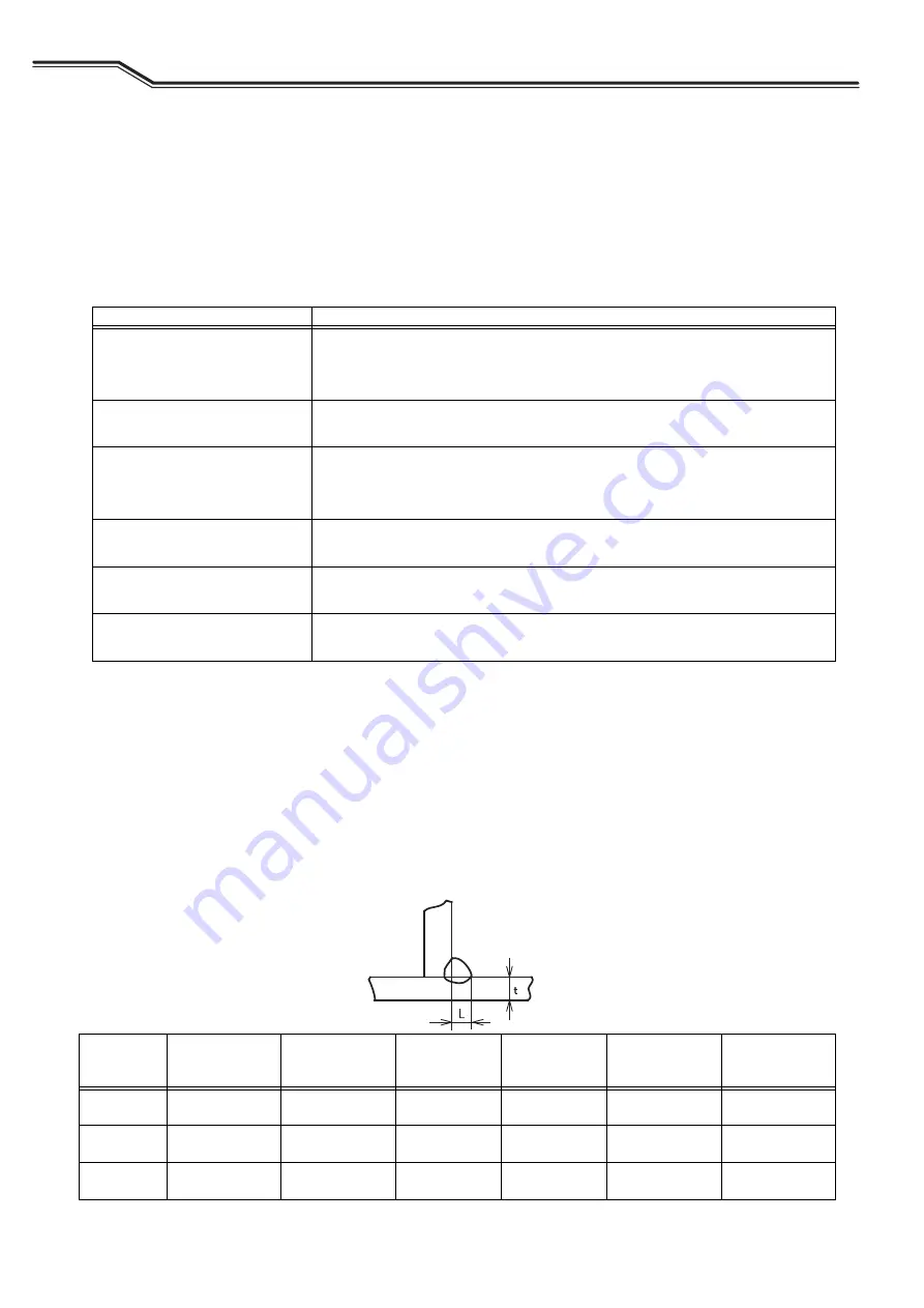
Example of welding conditions of horizontal fillet
Problem
Symptom
The wire feeding length is too long.
• The arc length becomes long.
• The bead width becomes wide.
• Shielding becomes poor.
The wire feeding length is too short.
• The arc length becomes short.
• Spatter is generated.
The welding voltage is too high.
• The arc length becomes long.
• The bead width becomes wide.
• Penetration and bead become small.
The welding voltage is too low.
• The wire contacts the base metal and spatter is generated.
• The bead width becomes narrow.
The welding current is too high.
• The bead width becomes wide.
• Penetration and bead become large.
The travel speed is too high.
• The bead width becomes narrow.
• Penetration and bead become small.
Plate
thickness
t [in. (mm)]
Leg length
L [in. (mm)]
Wire diameter
[in. (mm)
Φ
]
Current
(A)
Voltage
(V)
Travel speed
[IPM (cm/min)]
CO
2
-
gas flow rate
[CFH (L/min)]
18 ga. (1.2)
3/32 to 1/8
(2.5 to 3.0)
035, .040
(0.9, 1.0)
70 to 100
18 to 19
20 to 24
(50 to 60)
21 to 32
(10 to 15)
16 ga. (1.6)
3/32 to 1/8
(2.5 to 3.0)
.035 to .045
(0.9 to 1.2)
90 to 120
18 to 20
20 to 24
(50 to 60)
21 to 32
(10 to 15)
14 ga. (2.0)
1/8 to 9/64
(3.0 to 3.5)
.035 to .045
(0.9 to 1.2)
100 to 130
19 to 20
20 to 24
(50 to 60)
32 to 42
(15 to 20)


