background image

Structure 

The  door  station  (VTO)  has  six  models.  Different  models  have  different  front  panels  but  the 

same rear panel. 

 Dimensions (mm [inch]) 

Figure 1-1


Table 1-1 Component description 

No. 

Description 

No. 

Description 

White illuminator 

Keyboard 

MIC 

Loudspeaker 

Camera 

Fingerprint sensor 

Display 

Tamper button 

Card swiping area 

10 

Function  ports  (connected  to  locks,  access 

controllers, alarm in/out devices) 

Summary of Contents for VTO65 Series

Page 1: ...Digital Door Station VTO65 Series Quick Start Guide V1 0 0...

Page 2: ...operations that do not comply with the manual The manual would be updated according to the latest laws and regulations of related jurisdictions For detailed information refer to the paper manual CD RO...

Page 3: ...ease visit our website contact the supplier or customer service if there is any problem occurring when using the device If there is any uncertainty or controversy we reserve the right of final explana...

Page 4: ...revent liquids from flowing into the device Install the device at well ventilated places do not block its ventilation opening Use the device only within rated input and output range Do not dismantle t...

Page 5: ...face 6 4 2 Modifying IP Address 8 4 3 Selecting SIP Servers 8 4 4 4 4 1 Door Station VTO as SIP Server 9 4 4 2 Platform DSS Express DSS Pro as SIP Server 12 5 Engineering Setting 16 Entering Engineeri...

Page 6: ...rear panel Dimensions mm inch Figure 1 1 Table 1 1 Component description No Description No Description 1 White illuminator 6 Keyboard 2 MIC 7 Loudspeaker 3 Camera 8 Fingerprint sensor 4 Display 9 Tam...

Page 7: ...2 2 Cable Connection Cable connection Figure 2 1...

Page 8: ...ed dusty chemically corrosive places Engineering installation and test shall be done by professionals Do not dismantle or repair arbitrarily in case of device failure Contact after sales service Prepa...

Page 9: ...nting plate in the opening in the wall Step 3 Fix the mounting plate with cement or sealant Step 4 Connect cables Refer to 2 Cable Connection Step 5 Before connecting cables make sure that the power i...

Page 10: ...5 Apply silicone sealant Figure 3 3...

Page 11: ...or station you are operating works as the SIP server refer to 4 4 1 Door Station VTO as SIP Server 2 When the management platform works as the SIP server refer to 4 4 2 Platform DSS Express DSS Pro as...

Page 12: ...ng upper case lower case number and special character excluding Select the Email check box and then enter your email address Step 4 This email address is used to reset the password Click Next Step 5 T...

Page 13: ...nt the interface will go to the login interface automatically If PC IP address is not in the planned IP segment the interface will not go to the login interface You need to make the PC IP address in t...

Page 14: ...n VTO No 1 Each door station VTO has a unique number The numbers are normally the same as building numbers You can change the number of a door station VTO when it does not work as a SIP server Door st...

Page 15: ...4 4 1 2 Adding Indoor Monitors VTH When the door station VTO you are operating works as the SIP server you need to add all indoor monitors VTH to the door station VTO otherwise door stations VTO cann...

Page 16: ...room number configured at indoor monitor VTH When there are master indoor monitors VTH and extensions to realize group call function master indoor monitor VTH short No shall end with 0 and extension...

Page 17: ...m numbers of the second floor must be in the same form as those of the first floor For example room numbers of the first floor is 100 199 and room numbers of the second floor must be 200 299 Click Add...

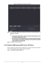
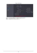
Page 18: ...13 SIP server Figure 4 9 Select Express DSS from the Server Type drop down list Step 2 Set parameters according to Table 4 3 Step 3...

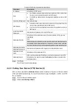
Page 19: ...f DSS Express or DSS Pro works as SIP server and alternate server is enabled when DSS Express or DSS Pro cannot work normally the door monitor VTO you are operating will be used as SIP server Alternat...

Page 20: ...nput box to enable the building No input function and then enter the No of the building where the door station is installed Unit No Unit No range is 0 9999 Click behind the input box to enable the bui...

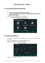
Page 21: ...ress project password on the door station VTO Step 1 The Engineering Setting interface is displayed Engineering setting Figure 5 1 Setting IP Address 5 2 You need to plan an IP address for the door st...

Page 22: ...Cancel to take a new image Only for VTO 6541H Fingerprint at most three fingerprints of one user can be recorded Each fingerprint needs to be recorded three times Operate according to voice prompt Iss...

Page 23: ...quirements of Faces Make sure that the face is clean and forehead is not covered by hair Do not wear glasses hats heavy beards or other face ornaments that influence face image recording With eyes ope...

Page 24: ...ance When importing face images through the management platform make sure that image pixels are more than 500 500 image size is less than 100 KB image format is JPG image background color is pure colo...

Page 25: ...a Do not put the fingerprint sensor at places with intense light high temperature and high humidity For the ones whose fingerprints are worn or are unclear try other unlock methods Fingers Recommended...

Page 26: ...21 Incorrect method Appendix Figure 2 3 Wrong finger pressing...

Page 27: ...firmware updates released by the manufacturer We suggest that you download and use the latest version of client software Nice to have recommendations to improve your equipment network security 1 Physi...

Page 28: ...Choose WPA2 PSK encryption mode and set up strong passwords 11 Audio and Video Encrypted Transmission If your audio and video data contents are very important or sensitive we recommend that you use en...

Page 29: ...24 so as to achieve the network isolation effect Establish the 802 1x access authentication system to reduce the risk of unauthorized access to private networks...

Reviews: