


Quick Start Guide
4
2
Network Configuration
Device initialization and IP address setting can be finished with the "ConfigTool" or in web interface.
For more information, see the
WEB operation manual
.
Device initialization is available on select models, and it is required at first use or after the device
being reset.
Device initialization is available only when the IP addresses of the device (192.168.1.108 by
default) and the PC stay in the same network segment.
Plan useable network segment properly to connect the device to the network.
The following figures and interfaces are for reference only, and the actual product shall prevail.
Initializing Device
2.1
Double-click "ConfigTool.exe" to open the tool.
Step 1
Click
.
Step 2
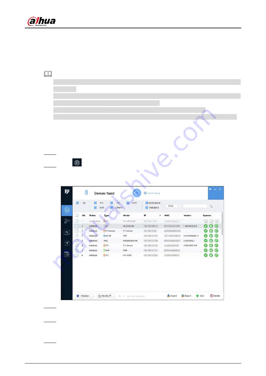
The
Modify IP
interface is displayed. See Figure 2-1.
Modify IP
Figure 2-1
Click
Search Setting
.
Step 3
The
Setting
interface is displayed.
Enter the start IP address and end IP address of the network segment in which you want to
Step 4
search devices, and then click
OK
.
All the devices found in the network segment are listed.
Select one or several devices with
Status
shows
Uninitialized
, and then click
Initialize
.
Step 5
The
Device initialization
interface is displayed.


