180
4.3 Preview
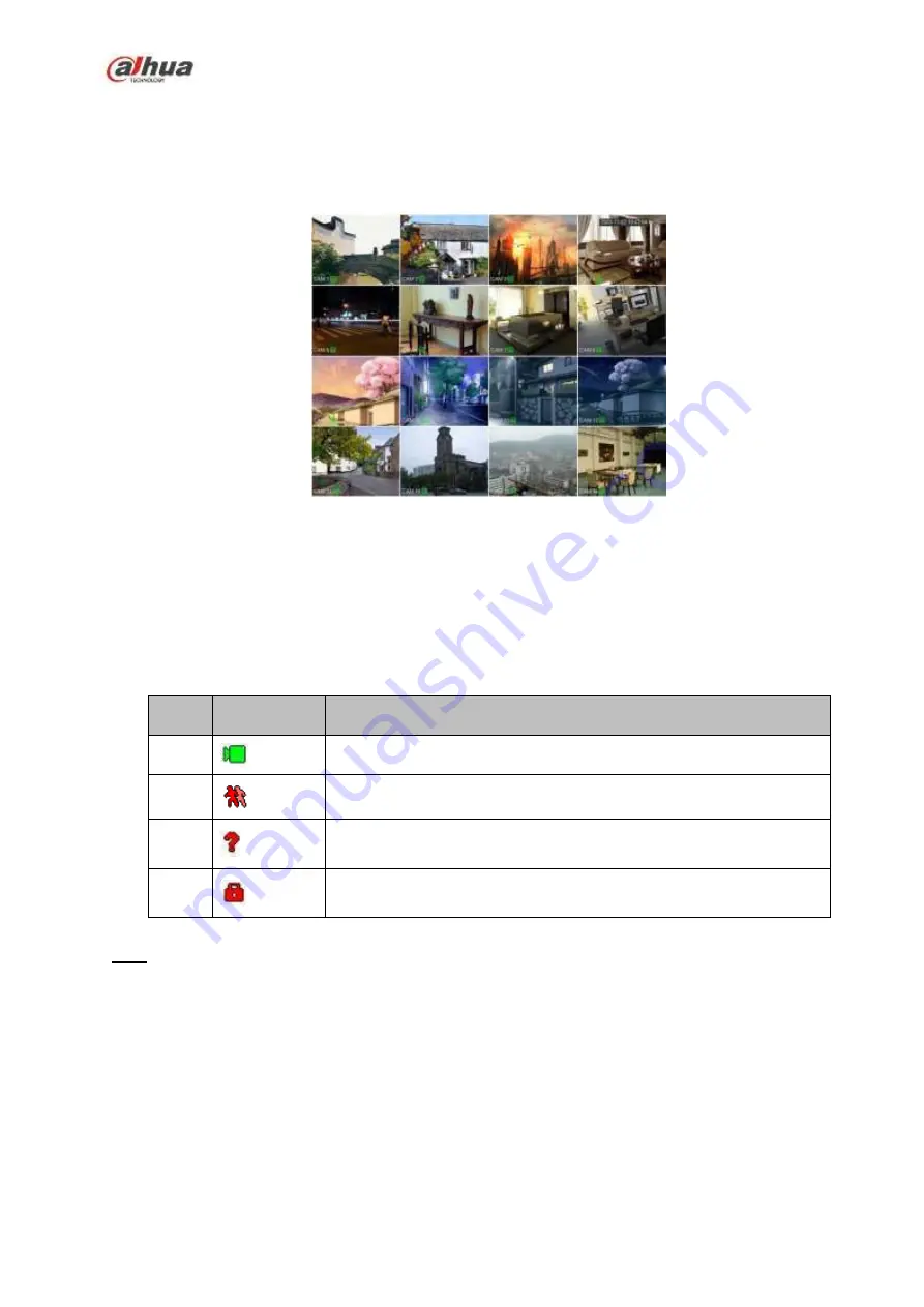
After device booted up, the system is in multiple-channel display mode. See Figure 4-57.Please note the
displayed window amount may vary. The following figure is for reference only. Please refer to chapter 1.3
Specifications for the window-amount your product supported.
Figure 4-57
4.3.1
Preview
If you want to change system date and time, you can refer to general settings (Main
Menu->Setting->System->General). If you want to modify the channel name, please refer to the
display settings (Main Menu->Camera->CAM name)
Please refer to the following sheet for detailed information.
SN
Icon
Function
1
When current channel is recording, system displays this icon.
2
When motion detection alarm occurs, system displays this icon.
3
When video loss alarm occurs, system displays this icon.
4
When current channel is in monitor lock status, system displays this
icon.
Tips
Preview drag: If you want to change position of channel 1 and channel 2 when you are
previewing, you can left click mouse in the channel 1 and then drag to channel 2, release mouse
you can switch channel 1 and channel 2 positions.
Use mouse middle button to control window split: You can use mouse middle button to switch
window split amount.
4.3.2
Navigation bar
On the preview interface, left click mouse, you can view the navigation bar. See Figure 4-58 or Figure
Summary of Contents for NVR1A-4P Series
Page 1: ...Dahua Network Video Recorder User s Manual V 4 3 0 ...
Page 142: ...128 Figure 3 11 3 6 12 NVR42V 8P Series Please refer to Figure 3 12 for connection sample ...
Page 143: ...129 Figure 3 12 ...
Page 157: ...143 Figure 4 15 Step 2 Click device display edit interface See Figure 4 16 ...
Page 220: ...206 Figure 4 93 Figure 4 94 ...
Page 240: ...226 Figure 4 110 Figure 4 111 Figure 4 112 ...
Page 251: ...237 Figure 4 123 Figure 4 124 ...
Page 253: ...239 Figure 4 126 Click draw button to draw the zone See Figure 4 127 ...
Page 257: ...243 Figure 4 130 Click Draw button to draw a zone See Figure 4 131 Figure 4 131 ...
Page 262: ...248 Figure 4 136 Click draw button to draw the zone See Figure 4 137 ...
Page 275: ...261 Figure 4 148 Figure 4 149 ...
Page 276: ...262 Figure 4 150 Figure 4 151 ...
Page 387: ...373 Figure 5 60 Figure 5 61 ...
Page 388: ...374 Figure 5 62 Figure 5 63 ...
Page 412: ...398 Figure 5 96 Figure 5 97 ...


