


30
2.4.3.1
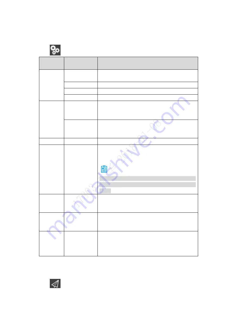
Settings
2.4.3.1.1
Aircraft Settings
Click
to go to the aircraft setting interface, as shown in Table 2-13.
Level
1
Menu
Level 2 Menu
Function
Preview
Remote control
View the mapping between the control stick and the
channel.
Flight mode
View aircraft flight mode.
Battery
View aircraft battery status.
Security
View aircraft security parameters.
Offline
map
Add new task
Add a new offline
map. Please refer to “6.3.3.1
” for detailed operation
methods.
Default Set
Default offline map of the system.
When the network connection is OK, system
automatically downloads current position map.
Settings
UI Settings
Set interface font size and style.
Pair
-
Pair aircraft, ground control station and remote
control. Please refer to “Appendix 3 System Pairing”
for detailed operation methods.
Note
All corresponding components have completed the
pairing process. Usually, it is unnecessary to pair
again.
Diagnosis -
Diagnose and repair the ground control station
system. Please refer to “3.9.1 Aircraft Diagnosis” for
detailed operation methods.
Options
-
Set offline map buffer. Please refer
to “6.3.3.3 Set
” for detailed operation
methods.
Register
-
Register relevant information and connect ITS
(Intelligent Transportation System) general control
platform
. Please refer to “4.5.2.2 Auto Registration”
for detailed operation methods.
Table 2-13
2.4.3.1.2
Preview Settings
Click
to enter preview setting interface.
Click the map preview window at the bottom left of the preview interface, to switch between the
video preview and map preview mode.
Summary of Contents for Navigator X820
Page 1: ...NAVIGATOR X820 User s Manual V1 0 1 ZHEJIANG DAHUA VISION TECHNOLOGY CO LTD ...
Page 18: ...5 Figure 2 2 ...
Page 21: ...8 2 2 1 Visible Light PTZ Camera 2 2 1 1 Dimensions Figure 2 4 ...
Page 22: ...9 Figure 2 5 ...
Page 24: ...11 2 2 2 Thermal PTZ Camera Optional 2 2 2 1 Dimensions Figure 2 7 ...
Page 25: ...12 Figure 2 8 ...
Page 27: ...14 2 3 Remote Control 2 3 1 Dimensions Figure 2 10 ...
Page 40: ...27 2 4 Ground Control Station GCS 2 4 1 Dimensions Figure 2 25 Figure 2 26 ...