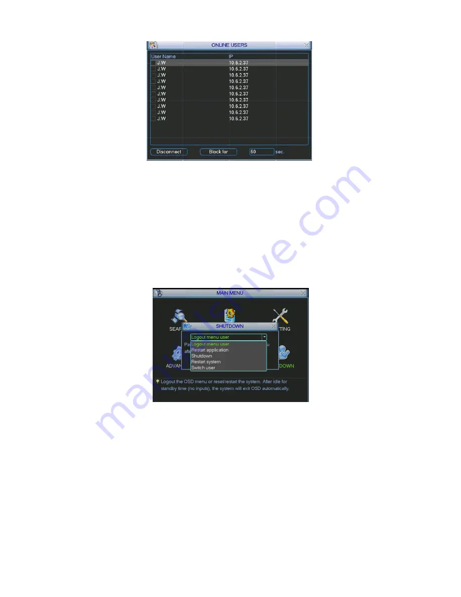
background image


118


Figure 5-55 

5.7


Shutdown 

Double click shutdown button, system pops up a dialogue box for you to select. See Figure 5-56 

z

  Logout menu user: log out menu. You need to input password when you login the next time. 

z

  Restart application: reboot DVR. 

z

  Shutdown: system shuts down and turns off power. 

z

   Restart system: system begins rebooting. 

z

  Switch user: you can use another account to log in. 


Figure 5-56 

Summary of Contents for N56 Series

Page 1: ...N56 Series Standalone DVR User s Manual Version 1 2 2 ...

Page 2: ...3 1 5U 16 1 3 4 2U 20 2 OVERVIEW AND CONTROLS 24 2 1 Front Panel 24 2 1 1 Mini 1U 1U Series 24 2 1 2 1 5U 2U 29 2 2 Rear Panel 32 2 2 1 Mini 1U Series 32 2 2 2 1U Series 35 2 2 3 1 5U Series 40 2 2 4 2U Series 40 2 3 Connection Sample 41 2 3 1 Mini 1U Series 41 2 3 2 1U Series 42 2 3 3 1 5U 43 2 3 4 2U 44 2 4 Remote Control 45 2 5 Mouse Control 47 ...

Page 3: ... 51 3 3 3 2U 51 3 4 Rack Installation 52 3 5 Connecting Power Supply 52 3 6 Connecting Video Input and Output Devices 53 3 6 1 Connecting Video Input 53 3 6 2 Connecting Video Output 53 3 7 Connecting Audio Input Output Bidirectional Audio 53 3 7 1 Audio Input 53 3 7 2 Audio Output 53 3 8 Alarm Input and Output Connection 54 3 8 1 Alarm Input and Output Details 54 3 8 2 Alarm Input Port 57 3 8 3 A...

Page 4: ...62 4 2 2 Manual record 62 4 3 Search Playback 64 4 4 Schedule 67 4 4 1 Schedule Menu 67 4 4 2 Snapshot 69 4 4 3 Image FTP 71 4 4 4 Snapshot Disk For special series only 71 4 5 Detect 72 4 5 1 Go to Detect Menu 72 4 5 2 Motion Detect 72 4 5 3 Video Loss 75 4 5 4 Camera Masking 75 4 6 Alarm Setup and Alarm Activation 76 4 6 1 Go to alarm setup interface 76 4 6 2 Alarm setup 76 4 7 Backup 78 4 7 1 De...

Page 5: ...ate Pattern Function 84 4 9 7 Auto Scan Setup 85 4 9 8 Activate Auto Scan 85 4 10 Flip 85 5 UNDERSTANDING OF MENU OPERATIONS AND CONTROLS 86 5 1 Menu Tree 86 5 2 Main Menu 86 5 3 Setting 87 5 3 1 General 87 5 3 2 Encode 89 5 3 3 Schedule 90 5 3 4 RS232 90 5 3 5 Network 91 5 3 6 Alarm 100 5 3 7 Detect 100 5 3 8 Pan Tilt Zoom 100 5 3 9 Display 101 5 3 10 Default 102 5 4 Search 103 5 5 Advanced 103 5...

Page 6: ...n 118 6 ABOUT AUXILIARY MENU 119 6 1 Go to Pan Tilt Zoom Menu 119 6 1 1 3D Intelligent Positioning Key 119 6 2 Preset Patrol Pattern Border Function 120 6 2 1 Preset Setup 121 6 2 2 Activate Preset 121 6 2 3 Patrol Setup 121 6 2 4 Activate Patrol 121 6 2 5 Pattern Setup 121 6 2 6 Activate Pattern Function 122 6 2 7 Border Setup 122 6 2 8 Activate Border Function 122 6 2 9 Flip 122 7 WEB CLIENT OPE...

Page 7: ... Configuration 138 7 5 3 Advanced 159 7 5 4 Additional Function 165 7 6 Search 168 7 7 Alarm 171 7 8 About 172 7 9 Log out 173 7 10 Un install Web Control 173 8 PROFESSIONAL SURVEILLANCE SYSTEM 174 9 FAQ 175 APPENDIX A HDD CAPACITY CALCULATION 180 APPENDIX B COMPATIBLE BACKUP DEVICE LIST 181 APPENDIX C COMPATIBLE CD DVD DEVICE LIST 186 APPENDIX D COMPATIBLE DISPLAYER LIST 187 ...

Page 8: ...vii APPENDIX E COMPATIBLE SWITCHER LIST 188 APPENDIX F COMPATIBLE WIRELESS MOUSE LIST 189 APPENDIX G EARTHING 190 APPENDIX H TOXIC OR HAZARDOUS MATERIALS OR ELEMENTS 195 ...

Page 9: ...ed to be a reference tool for the installation and operation of your system Here you can find information about this series DVR features and functions as well as a detailed menu tree Before installation and operation please read the following safeguards and warnings carefully ...

Page 10: ...ination and repair work should be done by the qualified service engineers We are not liable for any problems caused by unauthorized modifications or attempted repair 5 Environment The DVR should be installed in a cool dry place away from direct sunlight inflammable explosive substances and etc This series product shall be transported storage and used in the environment ranging from 0 to 55 6 Acces...

Page 11: ...sportation intelligent resident zone factory warehouse resources and water conservancy 1 2 Features This series product has the following features z Real time monitor It has analog output port VGA port and HDMI port You can use monitor or displayer to realize surveillance function System supports TV VGA HDMI output at the same time z Storage function Special data format to guarantee data security ...

Page 12: ...function z UPnP It is to establish the mapping relationship between the LAN and the WAN via the UPnP protocol Slight function differences may be found due to different series 1 3 Specifications 1 3 1 Mini 1U Series Parameter Simple Entry level Series Simple Lite Series Main Processor High performance industrial embedded micro controller OS Embedded LINUX System Resources Multiplex operations Multi...

Page 13: ...channel with black screen though system is encoding normally Screen lock function to prevent unauthorized user seeing secret video Channel Information Channel name recording status screen lock status video loss status and motion detection status are shown on the bottom left of display screen Video monitor Color Configuratio n Hue brightness contrast saturation and gain setup for each channel Audio...

Page 14: ...ze remote maintenance View alarm information such as external alarm motion detection and video loss via client Support network PTZ lens control File download backup and playback Multiple devices share information via corresponding software such as professional surveillance software PSS Duplex transparent COM Network alarm input and output Network Function Network control Bidirectional audio Motion...

Page 15: ...o the user or group amount Password modification Administrator can modify other user s password User Management Password Authenticati on Account lock strategy Five times login failure in thirty minutes may result in account lock Upgrade Web browser client end and update tool Password login protection to guarantee safety User friendly interface when login Provide the following options Logout shutdo...

Page 16: ...dard PAL 625 line 50f s NTSC 525 line 60f s Record Speed Real time Mode PAL 1f s to 25f s per channel and NTSC 1f s to 30f s per channel Video Partition 1 4 windows Optional 1 4 8 9 windows 1 4 8 9 16 windows Monitor Touring Support monitor tour functions such as alarm motion detection and schedule auto control PAL 625TV Line 50f s NTSC 525TV line 60f s Real time monitor D1 704 576 704 480 Playbac...

Page 17: ...g schedule recording Recording Length 1 to 120 minutes single record duration Default setup is 60 minutes Playback Repeat Way When hard disk is full system can overwrite previous video file Record Search Various search engines such as time type and channel Playback Mode Various fast play slow play speeds manual frame by frame playback and reverse play mode Various File Switch Ways Can switch to pr...

Page 18: ... 2 0 ports Max rated current is 800mA Network connection RJ45 10M 100 1000M self adaptable Ethernet port RS485 PTZ control port Support various PTZ control protocols Interface RS232 N A Hard Disk Information Display HDD current status Data Stream Statistics Data stream statistics for each channel in wave mode Log statistics Backup to 1024 log files Support various search engines such as time and t...

Page 19: ...iendly graphical user interface Input Devices Front panel USB mouse remote control Input Method Arabic number English character donation and extension Chinese optional System Shortcut Function Copy paste operation USB mouse right key shortcut menu double click USB mouse to switch screen Video Compressio n H 264 Compression Standard Audio Compressio n G 711A Video Input 4 CH composite video input N...

Page 20: ...52 288 352 240 QCIF 176 144 176 120 2 16 ch CIF 352 288 352 240 QCIF 176 144 176 120 Playback 1 ch D1 704 576 704 480 2CIF 352 576 352 480 HD1 704 288 704 240 CIF 352 288 352 240 QCIF 176 144 176 120 2 16 ch CIF 352 288 352 240 QCIF 176 144 17 6 120 Resolution PAL NTSC Support dual streams extra stream resolution CIF 352 288 352 240 QCIF 176 144 176 120 Support dual streams extra stream resolution...

Page 21: ...t Can switch to file on other channel of the same time If there is a file Support file continuous play when file is end system auto plays the next file in the current channel Multi channel Playback There are two playback modes 4 ch and full channel In 4 ch playback mode you can select the 1 2 3 4 ch playback according to your requirement In full channel mode system can playback in full channels Wi...

Page 22: ...put via network Hard Disk Information Display HDD current status Data Stream Statistics Data stream statistics for each channel in wave mode Log statistics Backup to 1024 log files Support various search engines such as time and type Version Display version information channel amount alarm input and output amount system version and release date System Information On line user Display current on li...

Page 23: ...use right key shortcut menu double click USB mouse to switch screen Video Compressio n H 264 Compression Standard Audio Compressio n G 711A Video Input 4 CH composite video input NTSC PAL BNC 1 0VB P P B75Ω 8 CH composite video input NTSC PAL BNC 1 0VB P P B75Ω 16 CH composite video input NTSC PAL BNC 1 0VB P P B75Ω 1 ch PAL NTSC BNC 1 0VP P 75Ω composite video signal output 1 ch VGA output 1 ch H...

Page 24: ...ecret channel with blue screen though system is encoding normally Screen lock function to prevent unauthorized user seeing secret video Channel Information Channel name recording status screen lock status video loss status and motion detection status are shown on the bottom left of display screen Color Configuratio n Hue brightness contrast saturation and gain setup for each channel Audio Input 1 ...

Page 25: ...nformation such as external alarm motion detection and video loss via client Support network PTZ lens control File download backup and playback Multiple devices share information via corresponding software such as professional surveillance software PSS Duplex transparent COM Network alarm input and output Network Function Network control Bidirectional audio Motion Detection Zone setup support 396 ...

Page 26: ...to guarantee safety User friendly interface when login Provide the following options Logout shutdown restart Login Logout and Shutdown Right authentication when shut down to make sure only those proper people can turn off DVR Power DC 12V Power Consumptio n 25W With adapter exclude HDD Working Temperatur e 0 55 Working Humidity 10 90 Air Pressure 86kpa 106kpa Dimension W D H 1U standard industrial...

Page 27: ...4 480 Playback 1 2 ch D1 704 576 704 480 HD1 704 288 704 240 2CIF 352 576 352 480 CIF 352 288 352 240 QCIF 176 144 176 120 3 4 ch CIF 352 288 352 240 QCIF 176 144 176 120 Playback 1 2 ch D1 704 576 704 480 2CIF 352 576 352 480 HD1 704 288 704 240 CIF 352 288 352 240 QCIF 176 144 176 120 3 8 ch CIF 352 288 352 240 QCIF 176 144 176 120 Playback 1 ch D1 704 576 704 480 2CIF 352 576 352 480 HD1 704 28...

Page 28: ...nel Playback Mode Various fast play slow play speeds manual frame by frame playback and reverse play mode Various File Switch Ways Can switch to previous or next file or any file in current play list Can switch to file on other channel of the same time If there is a file Support file continuous play when file is end system auto plays the next file in the current channel Multi channel Playback Ther...

Page 29: ...M input and output via network Hard Disk Information Display HDD current status Data Stream Statistics Data stream statistics for each channel in wave mode Log statistics Backup to 1024 log files Support various search engines such as time and type Version Display version information channel amount alarm input and output amount system version and release date System Information On line user Displa...

Page 30: ...key shortcut menu double click USB mouse to switch screen Video Compressio n H 264 Compression Standard Audio Compressio n G 711A Video Input 4 CH composite video input NTSC PAL BNC 1 0VB P P B75Ω 8 CH composite video input NTSC PAL BNC 1 0VB P P B75Ω 16 CH composite video input NTSC PAL BNC 1 0VB P P B75Ω 1 ch PAL NTSC BNC 1 0VP P 75Ω composite video signal output 1 ch VGA output 1 ch HDMI output...

Page 31: ...rmation and privacy mask zone TV Adjust Adjust TV output zone suitable to anamorphic video Channel Lock Cover secret channel with blue screen though system is encoding normally Screen lock function to prevent unauthorized user seeing secret video Channel Information Channel name recording status screen lock status video loss status and motion detection status are shown on the bottom left of displa...

Page 32: ...remotely DVR configuration through client end and web browser Upgrade via client or browser to realize remote maintenance View alarm information such as external alarm motion detection and video loss via client Support network PTZ lens control File download backup and playback Multiple devices share information via corresponding software such as professional surveillance software PSS Duplex transp...

Page 33: ...r Manageme nt Support user group and its corresponding rights modification No limit to the user or group amount Password modification Administrator can modify other user s password User Management Password Authenticati on Account lock strategy Five times login failure in thirty minutes may result in account lock Upgrade Web browser client end and update tool Password login protection to guarantee ...

Page 34: ...l button information Name Icon Function Power button Power button press this button for three seconds to boot up or shut down DVR Shift Shift In textbox click this button to switch between numeral English Small Capitalized donation and etc Activate current control modify setup and then move up and down Increase decrease numeral Assistant function such as PTZ menu Up 1 Down 4 S T In text mode input...

Page 35: ...acter small capitalized and etc Assistant Fn Realize other special functions Fast play 7 Various fast speeds and normal playback In text mode input number 7 English character P Q R S Play previous 0 _ In playback mode playback the previous video In text mode input number 0 Reverse Pau se 6 W In normal playback or pause mode click this button to reverse playback In reverse playback click this butto...

Page 36: ...R Activate current control modify setup and then move up and down Increase decrease numeral Up Down S T Assistant function such as PTZ menu Shift current activated control Left Right W X When playback click these buttons to control playback bar Go to previous menu or cancel current operation ESC ESC When playback click it to restore real time monitor mode Confirm current operation Go to default bu...

Page 37: ...ht become off when the external alarm stops The front panel of another 1U series product is shown as in Figure 2 4 Figure 2 4 Please refer to the following sheet for front panel button information Name Icon Function Power button Power button press this button for three seconds to boot up or shut down DVR Shift Shift In textbox click this button to switch between numeral English Small Capitalized d...

Page 38: ...er special functions Fast play 7 Various fast speeds and normal playback In text mode input number 7 English character P Q R S Play previous 0 _ In playback mode playback the previous video In text mode input number 0 Reverse Pau se 6 W In normal playback or pause mode click this button to reverse playback In reverse playback click this button to pause playback In text mode input number 6 English ...

Page 39: ... down DVR Shift Shift In textbox click this button to switch between numeral English Small Capitalized donation and etc Activate current control modify setup and then move up and down Increase decrease numeral Assistant function such as PTZ menu Up 1 Down 4 S T In text mode input number 1 4 English character G H I Shift current activated control Left 2 Right 3 W X When playback click these buttons...

Page 40: ... click this button to reverse playback In reverse playback click this button to pause playback In text mode input number 6 English character M N O Play Next 9 f In playback mode playback the next video In menu setup go to down ward of the dropdown list In text mode input number 9 English character W X Y Z Play Pause 5 f In normal playback click this button to pause playback In pause mode click thi...

Page 41: ...Shift current activated control and then move left and right Left Right W X When playback click these buttons to control playback bar Go to previous menu or cancel current operation ESC ESC When playback click it to restore real time monitor mode Confirm current operation Go to default button Enter ENTER Go to menu Record REC Manually stop start recording working with direction keys or numeral key...

Page 42: ...se playback In pause mode click this button to resume playback Window switch Mult Click it to switch one window multiple window Shuttle outer ring In real time monitor mode it works as left right direction key Playback mode counter clockwise to forward and clock wise to backward Jog inner dial Up down direction key Playback mode turn the inner dial to realized frame by frame playback Only applies ...

Page 43: ... 5 On off button 6 Video output 7 Network port 8 HDMI port 9 USB port 10 Power socket 2 2 1 2 Simple Entry level Series The simple entry level series rear panel is shown as below See Figure 2 8 Figure 2 8 Please refer to the following sheet for detailed information 1 Video input 2 Audio input 3 Audio output 4 Video VGA output 5 On off button 6 Video output 7 Network port 8 HDMI port 9 USB port 10 ...

Page 44: ...ideo input 2 Video output 3 Video VGA output 4 HDMI port 5 USB port 6 Network port 7 RS 485 port 8 Power socket 9 Alarm input alarm output 10 GND port 11 Audio output 12 Audio input 13 On off button The rear panel of the 8 channel series product is shown as in Figure 2 10 Figure 2 10 Please refer to the following sheet for detailed information 1 Video input 2 Video output 3 Audio output 4 Audio in...

Page 45: ... shown as in Figure 2 11 Figure 2 11 Please refer to the following sheet for detailed information 1 Video input 2 Video output 3 Audio output 4 Audio input 5 Alarm input alarm output 6 On off button 7 Video VGA output 8 HDMI port 9 USB port 10 Network port 11 RS 485 port 12 Power socket 13 GND port 2 2 2 1U Series 2 2 2 1 Full D1 Series The rear panel is shown as in Figure 2 12 ...

Page 46: ... port 10 Video VGA output 11 RS232 port 12 On off button 13 GND port 2 2 2 2 4 ch 2CIF Real time Series This series DVR rear panel is shown as below See Figure 2 13 Figure 2 13 Please refer to the following sheet for detailed information 1 Video input 2 Audio input 3 Audio output 4 Video output 5 USB port 6 HDMI port 7 Network port 8 Power socket 9 Alarm input alarm output RS485 port 10 Video VGA ...

Page 47: ...eo output 5 Video VGA output 6 HDMI port 7 RS232 port 8 USB port 9 Network port 10 Alarm input alarm output RS485 port 11 Power socket 12 On off button 13 GND port 2 2 2 4 4 ch Audio CIF Real time Series This series DVR rear panel is shown as below See Figure 2 15 Figure 2 15 Please refer to the following sheet for detailed information 1 Video input 2 1st to 4th channel audio input 3 Audio output ...

Page 48: ...Please refer to the following sheet for detailed information 1 Video input 2 1st to 4th channel audio input 3 Audio output 4 Video output 5 Video VGA output 6 HDMI port 7 RS232 port 8 USB port 9 Network port 10 Alarm input Alarm output RS485 port 11 On off button 12 Power socket 13 GND port 14 D sub port 5th to 16th channel audio input port 2 2 2 6 CIF Real time Series The 4 channel series DVR rea...

Page 49: ...nel series DVR rear panel is shown as below See Figure 2 18 Figure 2 18 Please refer to the following sheet for detailed information 1 Video input 2 Audio input 3 Audio output 4 Video output 5 Video VGA output 6 HDMI port 7 USB port 8 Network port 9 RS485 port 10 Power socket 11 Alarm input Alarm output 12 On off button 13 GND port The 16 channel series DVR rear panel is shown as below See Figure ...

Page 50: ...ure 2 20 Figure 2 20 Please refer to the following sheet for detailed information 1 GND port 2 Power socket 3 On off button 4 Fan 5 Audio input matrix video output loop video output 6 Video input 7 Video CVBS output 8 Bidirectional talk output 9 Bidirectional talk input 10 Audio output 11 Alarm input Alarm output RS485 port 12 Video VGA output 13 HDMI port 14 RS232 port 15 eSATA port 16 USB port 1...

Page 51: ... output 12 Bidirectional talk input 13 Bidirectional talk output 14 Alarm input Alarm output RS485 port 15 Video VGA output 16 HDMI port 17 RS 232 port 18 eSATA port 19 USB port 20 Network port When connect the Ethernet port please use crossover cable to connect the PC and use the straight cable to connect to the switcher or router 2 3 Connection Sample 2 3 1 Mini 1U Series Please refer to Figure ...

Page 52: ...42 Figure 2 22 2 3 2 1U Series Please refer to Figure 2 23 for connection sample Please note the following interface is based on the 2CIF real time series product ...

Page 53: ...43 Figure 2 23 2 3 3 1 5U The connection sample is shown as in Figure 2 24 Please note the following figure is based on the 16 channel series product ...

Page 54: ...44 Figure 2 24 2 3 4 2U The connection sample is shown as in Figure 2 25 Please note the following figure is based on the 16 channel series product ...

Page 55: ...45 Figure 2 25 2 4 Remote Control The remote control interface is shown as in Figure 2 26 Please note remote control is not our standard accessory and it is not included in the accessory bag ...

Page 56: ...Multiple slow play speeds or normal playback 5 Next record In playback mode playback the next video 6 Previous record In playback mode playback the previous video In pause mode click this button to realize normal playback In normal playback click this button to pause playback 7 Play Pause In real time monitor mode click this button to enter video search menu Reverse playback pause mode click this ...

Page 57: ...ultiple window switch Switch between multiple window and one window In 1 ch monitor mode pop up assistant function PTZ control and Video color Switch the PTZ control menu in PTZ control interface 14 Auxiliary key In motion detection interface working with direction keys to complete setup Input password channel or switch channel 15 0 9 number key Shift is the button to switch the input method 2 5 M...

Page 58: ...st to playback the video Double left click mouse In multiple window mode double left click one channel to view in full window Double left click current video again to go back to previous multiple window mode In real time monitor mode pops up shortcut menu one window four window nine window and sixteen window Pan Tilt Zoom color setting search record alarm input alarm output main menu Among which P...

Page 59: ...he text column the text is shown as blue input button pops up on the right Click that button to switch between numeral input and English input capitalized and small Use or to shift between small character and capitalized character 2 6 2 Front Panel Move the cursor to the text column Click Fn key and use direction keys to select number you wanted Please click enter button to input ...

Page 60: ...el and Rear Panel The model label in the front panel is very important please check according to your purchase order The label in the rear panel is very important too Usually we need you to represent the serial number when we provide the service after sales 3 3 HDD Installation You can refer to the Appendix for recommended HDD brand Usually we do not recommend the PC HDD Please use HDD of 7200rpm ...

Page 61: ...he side panel 1 Loosen the screws of the upper cover 2 Line up the HDD to the four holes of the HDD bracket 3 Use four screws to fix HDD 4 Unfasten the HDD power cable 5 Use the special data cable to connect the HDD and the SATA port 6 Insert the HDD power cable Close the chassis and fix the screws to secure firmly 2 Remove the HDD upper bracket 3 Now you can see the bottom bracket 1 Loosen the sc...

Page 62: ... sound ventilation z Please install from the bottom to the top z If there are more accessories connected in the rack please take precaution measures in case the rack power is overload 3 5 Connecting Power Supply Please check input voltage and device power button match or not We recommend you use UPS to guarantee steady operation DVR life span and other peripheral equipments operation such as camer...

Page 63: ... high tension current Keep connection lugs in well contactBTTTB The signal line and shielded wire should be fixed firmly and in well connection Avoid dry joint lap welding and oxidation BTTTB 3 6 2 Connecting Video Output Video output includes a BNC PAL NTSC1 0VP P 75Ω output a VGA output and HDMI output System supports BNC VGA and HDMI output at the same time When you are using pc type monitor to...

Page 64: ...larm output port should not be connected to high power load directly It shall be less than 1A to avoid high current which may result in relay damage Please use the co contactor to realize the connection between the alarm output port and the load 3 How to connect PTZ decoder a Ensure the decoder has the same grounding with DVR otherwise you may not control the PTZ Shielded twisted wire is recommend...

Page 65: ... 1 2 8 16 channel 1U Series The interface is shown as in Figure 3 2 Figure 3 2 Please refer to the following sheet and Figure 3 2 for detailed information Parameter Grounding Alarm GND Alarm Input 1 2 16 It becomes valid in low voltage 1 NO C 2 NO C 3 NO C Three NO activation outputs 485 A B 485 communication port They are used to control devices such as PTZ Please parallel connect 120Ω between A ...

Page 66: ... output on off button Earth cable 485 A B 485 communication port They are used to control devices such as PTZ Please parallel connect 120TΩ between A B cables if there are too many PTZ decoders 3 8 1 4 1 5U Series You can refer to the following sheet and X288H288H288HFigure 3 6X for alarm input and output information Figure 3 6 In the first line from the left to the right 1 2 3 4 5 6 7 8 9 10 ALAR...

Page 67: ...following sheet and X288H288H288HFigure 3 6X for alarm input and output information Figure 3 7 In the first line from the left to the right 1 2 3 4 5 6 7 8 9 10 11 12 13 14 15 16 ALARM 1 to ALARM 16 The alarm becomes active in low voltage In the second line from the left to the right NO1 C1 NO2 C2 NO3 C3 NO4 C4 NO5 C5 NC5 The first four are four groups of normal open activation output on off butto...

Page 68: ...ce z To avoid overloading please read the following relay parameters sheet carefully z RS485 A B cable is for the A B cable of the PTZ decoder Relay Specification Model JRC 27F Material of the touch Silver Rated switch capacity 30VDC 2A 125VAC 1A Maximum switch power 125VA 160W Maximum switch voltage 250VAC 220VDC Rating Resistance Load Maximum switch currency 1A Between touches with same polarity...

Page 69: ...k 3 10 RS485 When the DVR receives a camera control command it transmits that command up the coaxial cable to the PTZ device RS485 is a single direction protocol the PTZ device can t return any data to the unit To enable the operation connect the PTZ device to the RS485 A B input on the DVR See X289H289H289HFigure 3 8X Since RS485 is disabled by default for each camera you must enable the PTZ sett...

Page 70: ...p wizard interface Here you can set the system basic information See Figure 4 1 Figure 4 1 The system login interface is shown as in Figure 4 2 System consists of four accounts z Username admin Password admin administrator local and network z Username 888888 Password 888888 administrator local only z Username 666666 Passwords 666666 Lower authority user who can only monitor playback backup and etc...

Page 71: ...anced and shutdown You can move the cursor to highlight the icon and then double click mouse to enter the sub menu Figure 4 3 4 1 3 Logout There are two ways for you to log out One is from menu option In the main menu click shutdown button you can see an interface is shown as below See Figure 4 4 Figure 4 4 There are several options for you See Figure 4 5 Figure 4 5 ...

Page 72: ...r you logged in the system is in live viewing mode You can see system date time and channel name If you want to change system date and time you can refer to general settings Main Menu Setting General If you want to modify the channel name please refer to the display settings Main Menu Setting Display Preview Zoom Function Move your mouse to the left top corner of the preview interface you can see ...

Page 73: ...e Channel records as you have set in recording setup Main Menu Setting Schedule z Stop All channels stop recording Figure 4 7 4 2 2 3 Enable disable record Please check current channel status means it is not in recording status means it is in recording status You can use mouse or direction key to highlight channel number See Figure 4 8 Figure 4 8 4 2 2 4 Enable all channel recording Highlight belo...

Page 74: ... manual record now Figure 4 10 4 2 2 5 Stop all channel recording Please highlight ALL after Stop See Figure 4 11 System stops all channel recording no matter what mode you have set in the menu Main menu Setting Schedule Figure 4 11 4 3 Search Playback Click search button in the main menu search interface is shown as below See Figure 4 12 Usually there are three file types z R Regular recording fi...

Page 75: ...herwise there is no picture or file zIn any play mode click the date you want to see you can see the corresponding record file trace in the time bar 4 Playback mode and channel selection pane zPlayback mode 1 4 9 16 It may vary due to different series In 1 window playback mode you can select 1 16 channels In 4 window playback mode you can select 4 channels according to your requirement In 9 window...

Page 76: ... normal play mode when you pause current play you can click W and X to begin frame by frame playback In frame by frame playback mode click to restore normal playback Slow play In playback mode click it to realize various slow play modes such as slow play 1 slow play 2 and etc Fast forward In playback mode click to realize various fast play modes such as fast play 1 fast play 2 and etc Note The act...

Page 77: ... switch the play file z Operations such as set time bar click the play button or any file list operation will stop current motion detect play Other Functions 14 Other channel synchronization switch to play when playback When playing the file click the number button system can switch to the same period of the corresponding channel to play 15 Digital zoom When the system is in full screen playback m...

Page 78: ...ing in channel 1 you can click paste button and turn to channel 2 and then click copy button You can finish setting for one channel and then click save button or you can finish all setup and then click save button to memorize all the settings 4 4 1 2 Redundancy Please note for the product of only one HDD it does not support the redundancy function Redundancy function allows you to memorize record ...

Page 79: ...nt disk There are two ways for you to playback or search in the redundant disk z Set redundant disk s as read only disk or read write disk Main menu Advanced HDD management See Figure 4 14 System needs to reboot to get setup activated Now you can search or playback file in redundant disk z Dismantle the disk and play it in another PC 4 4 2 Snapshot 4 4 2 1 Schedule Snapshot In Encode interface cli...

Page 80: ...arm occurred z In Encode interface click snapshot button to input snapshot mode size quality and frequency z In General interface please input upload interval z In Detect interface please enable snapshot function for specified channels Or in alarm interface please enable snapshot function for specified channels Please refer to the following figure for detailed information See Figure 4 16 Figure 4 ...

Page 81: ...responding FTP server Please enable schedule snapshot Chapter 4 4 2 1 or activation snapshot Chapter 4 4 2 2 first now system can upload the image file to the FTP server Figure 4 17 4 4 4 Snapshot Disk For special series only Set one disk as snapshot Main menu Advanced HDD management and then click execute button See Figure 4 18 System needs to reboot to get current setup activated Figure 4 18 All...

Page 82: ...ct motion detection type z Channel Select a channel from the dropdown list to set motion detect function z Enable Check the box here to enable motion detect function z Region Click select button the interface is shown as in Figure 4 21 Here you can set motion detection zone There are 396 PAL 330 NTSC small zones The green zone is current cursor position Grey zone is the motion detection zone Black...

Page 83: ...d channel System auto activates motion detection channel s to record once an alarm occurs Please make sure you have set MD record in Schedule interface Main Menu Setting Schedule and schedule record in manual record interface Main Menu Advanced Manual Record z PTZ activation Here you can set PTZ movement when alarm occurs Such as go to preset tour pattern when there is an alarm Click select button...

Page 84: ...74 Figure 4 20 Figure 4 21 Figure 4 22 ...

Page 85: ...can enable alarm output channel and then enable show message function Tips You can enable preset tour pattern activation operation when video loss occurs Please refer to chapter 4 5 2 motion detection for detailed information Figure 4 25 4 5 4 Camera Masking When someone viciously masks the lens or the output video is in one color due to the environments light change the system can alert you to gu...

Page 86: ...les camera masking function during the period you set here It is null for motion detect or video loss type Figure 4 26 4 6 Alarm Setup and Alarm Activation Before operation please make sure you have properly connected alarm devices such as buzzer 4 6 1 Go to alarm setup interface In the main menu from Setting to Alarm you can see alarm setup interface See Figure 4 27 4 6 2 Alarm setup Alarm interf...

Page 87: ... schedule interface Main Menu Setting Schedule and select schedule record in manual record interface Main Menu Advance Manual Record z Latch Here is for you to set proper delay duration Value ranges from 10 to 300 seconds System automatically delays specified seconds in turning off alarm and activated output after external alarm cancelled z Tour Here you can enable tour function when alarm occurs ...

Page 88: ...r to Chapter 7 Web Client Operation for network download backup operation 4 7 1 Detect Device Click backup button you can see an interface is shown as in Figure 4 31 Here is for you to view devices information You can view backup device name and its total space and free space The device includes USB burner flash disk SD card and portable HDD ...

Page 89: ...bar for you reference When the system completes backup you can see a dialogue box prompting successful backup Figure 4 32 Click backup button system begins burning At the same time the backup button becomes stop button You can view the remaining time and process bar at the left bottom z File format Click the file format you can see there are two options DAV ASF z Picture backup Please set the corr...

Page 90: ...ols there might be a little difference 4 8 1 Cable Connection Please follow the procedures below to go on cable connection z Connect the dome RS485 port to DVR 485 port z Connect dome video output cable to DVR video input port z Connect power adapter to the dome 4 8 2 PTZ Setup Note The camera video should be in the current screen Before setup please check the following connections are right z PTZ...

Page 91: ... Button in the front panel or click Fn key in the remote control The interface is shown as in Figure 4 35 Figure 4 35 Click Pan Tilt Zoom the interface is shown as below See Figure 4 36 Here you can set the following items z Step value ranges fro 1 to 8 z Zoom z Focus z Iris Please click icon and to adjust zoom focus and iris ...

Page 92: ...key system goes back to the single screen mode Drag the mouse in the screen to adjust section size The dragged zone supports 4X to 16X speeds It can realize PTZ automatically The smaller zone you dragged the higher the speed Figure 4 38 Here is a sheet for you reference Name Function key function Shortcut key Function key function Shortcut Key Zoom Near Far Focus Near _ Far Iris close W Open f 4 9...

Page 93: ...rol parameter You can define it as you require z You need to refer to your speed dome user s manual for Aux definition In some cases it can be used for special process z The following setups are usually operated in the X332H332H332HFigure 4 36 Figure 4 39 and Figure 4 40 4 9 1Preset Setup In Figure 4 36 use eight direction arrows to adjust camera to the proper position In Figure 4 39 click preset ...

Page 94: ... 4 42 4 9 4 Activate Patrol tour In X341H341H341H Figure 4 39 input patrol tour number in the No blank and click patrol button 4 9 5 Pattern Setup In Figure 4 39 click pattern button and then click begin button The interface is shown as in Figure 4 43 Then you can go to Figure 4 36 X to modify zoom focus and iris Go back to Figure 4 43 and click end button You can memorize all these operations as ...

Page 95: ...procedures to set right limit Figure 4 44 4 9 8 Activate Auto Scan In Figure 4 40 click Auto Scan button the system begins auto scan Correspondingly the auto scan button becomes Stop button Click stop button to terminate scan operation 4 10 Flip In Figure 4 40 click page switch button you can see an interface is shown as below See Figure 4 45 Here you can set auxiliary function The aux value has r...

Page 96: ...t for simple lite series Detect Pan Tilt Zoom Display Default Search Advanced HDD Management Alarm Output Abnormity Manual Record Account Auto Maintain TV Adjust Title Overlay Config Backup Shutdown 5 2 Main Menu After you logged in the system main menu is shown as below See Figure 5 1 X There are total six icons search Information setting backup advanced and shutdown Move the cursor to highlight ...

Page 97: ...ou can see an interface is shown as in Figure 5 4 Here you can set start time and end time by setting corresponding week setup In Figure 5 4 enable date button you can see an interface is shown as in Figure 5 5 Here you can set start time and end time by setting corresponding date setup z Time format There are two types 24 hour mode or 12 hour mode z Language System supports various languages Chin...

Page 98: ...mats NTSC and PAL z Auto logout Here is for you to set auto logout interval once login user remains inactive for a specified time Value ranges from 0 to 60 minutes z Startup wizard Once you check the box here system will go to the startup wizard directly when the system restarts the next time Otherwise it will go to the login interface z Device ID Please input a corresponding device name here Note...

Page 99: ...ies and full D1 series product The frame rate ranges from 1f s to 25f s in PAL mode and 1f s to 30f s in NTSC mode For 4 ch 2CIF real time series product 4 channel CIF entry level series product 4 ch CIF real time 1U series 4 chanel 1 5U series product 4 channel 2U series product The resolution of 1 channel supports D1 HD1 2CIF CIF QCIF frame rate 25 30fps the resolution of rest channels 2 channel...

Page 100: ...nding position in the screen Channel display You can select system displays channel number or not when you playback Please click set button and then drag the title to the corresponding position in the screen Please highlight icon to select the corresponding function Figure 5 6 Figure 5 7 5 3 3 Schedule Please refer to chapter 4 4 schedule 5 3 4 RS232 RS232 interface is shown as below There are fiv...

Page 101: ...ation z IP address Here you can input IP address z DHCP It is to auto search IP When enable DHCP function you can not modify IP Subnet mask Gateway These values are from DHCP function If you have not enabled DHCP function IP Subnet mask Gateway display as zero You need to disable DHCP function to view current IP information Besides when PPPoE is operating you can not modify IP Subnet mask Gateway ...

Page 102: ...dvanced setup interface is shown as in Figure 5 10 Please draw a circle to enable corresponding function and then double click current item to go to setup interface Figure 5 10 5 3 5 2 IP Filter IP filter interface is shown as in Figure 5 11 You can add IP in the following list The list supports max 64 IP addresses Please note after you enabled this function only the IP listed below can access cur...

Page 103: ...alue is 123 z Update interval minimum value is 1 Max value is 65535 Unit minute z Time zone select your corresponding time zone here Here is a sheet for your time zone setup City Region Name Time Zone London GMT 0 Berlin GMT 1 Cairo GMT 2 Moscow GMT 3 New Deli GMT 5 Bangkok GMT 7 Beijing Hong Kong GMT 8 Tokyo GMT 9 Sydney GMT 10 Hawaii GMT 10 Alaska GMT 9 Pacific Time P T GMT 8 American Mountain T...

Page 104: ...bit of the first byte 1110 z Reserved local multiple cast group address 224 0 0 0 224 0 0 255 TTL 1 When sending out telegraph For example 224 0 0 1 All systems in the sub net 224 0 0 2 All routers in the sub net 224 0 0 4 DVMRP router 224 0 0 5 OSPF router 224 0 0 13 PIMv2 router z Administrative scoped addressees 239 0 0 0 239 255 255 255 Private address space z Like the single broadcast address...

Page 105: ...er rebooting DVR will connect to internet automatically The IP in the PPPoE is the DVR dynamic value You can access this IP to visit the unit Figure 5 14 5 3 5 6 DDNS Setup DDNS setup interface is shown as in Figure 5 15 You need a PC of fixed IP in the internet and there is the DDNS software running in this PC In other words this PC is a DNS domain name server In network DDNS please select DDNS t...

Page 106: ...hows Success z Router LAN IP It is the router IP in the LAN z WAN IP It is the router IP in the WAN z Port Mapping list The port mapping list here is the one to one relationship with the router s port mapping setting z Enable Switch It shows that the function of port mapping is enabled in this port z List Service name Defined by user Protocol Protocol type Internal port Port that has been mapped i...

Page 107: ...box z Password Please input the corresponding password here z Sender Please input sender email box here z Title Please input email subject here System support English character and Arabic number Max 32 digit z Receiver Please input receiver email address here System max supports 3 email boxes z SSL enable System supports SSL encryption box z Interval The send interval ranges from 0 to 3600 seconds...

Page 108: ...e abnormity event activates the email system sends out the email according to the interval you specified here This function is very useful when there are too many emails activated by the abnormity events which may result in heavy load for the email server Figure 5 18 Figure 5 19 5 3 5 9 FTP You need to download or buy FTP service tool such as Ser U FTP SERVER to establish FTP service Please instal...

Page 109: ... FTP server address port and remote directory When remote directory is null system automatically create folders according to the IP time and channel User name and password is the account information for you to login the FTP File length is upload file length When setup is larger than the actual file length system will upload the whole file When setup here is smaller than the actual file length syst...

Page 110: ... the following items Please select channel first See Figure 5 24 z Protocol Select corresponding PTZ protocol such as PELCOD z Address input corresponding PTZ address z Baud rate Select baud rate z Data bit Select data bit z Stop bit Select stop bit z Parity There are three choices none odd even After completed all the setups please click save button system goes back to the previous menu For detai...

Page 111: ...el name or not when system is playback z Resolution There are four options 1920 1080 1280 1024 default 1280 720 1024 768 Please note the system needs to reboot to activate current setup z Enable tour Activate tour function z Interval System supports 1 4 8 9 16 window tour Input proper interval value here The value ranges from 5 120 seconds In tour process you can use mouse or click Shift to turn o...

Page 112: ...need to refresh web or client end to get the latest channel name System max support 25 digital character Figure 5 26 In tour mode you can see the following interface On the right corner right click mouse or click shift button you can control the tour There are two icons stands for enabling window switch and stands for disabling window function See Figure 5 27 Figure 5 27 5 3 10 Default ...

Page 113: ...he setups please click save button system goes back to the previous menu Warning System menu color language time display mode video format IP address user account will not maintain previous setup after default operation Figure 5 28 5 4 Search Please refer to chapter 4 3 Search 5 5 Advanced Double click advanced icon in the main window the interface is shown as below See Figure 5 29 There are total...

Page 114: ...shown as X z Alarm set Click alarm set button the interface is shown as below See Figure 5 31 This interface is just like the abnormity setup Please refer to chapter 5 5 2 for detailed information z HDD operation You can select HDD mode from the dropdown list such as read only or you can erase all data in the HDD Please note system needs to reboot to get all the modification activated Figure 5 30 ...

Page 115: ...up operation of the read write HDDs It is not for the redundancy HDD HDD Setting Click the button HDD Settings at the top right corner of the Figure 5 30 system will pop up an interface as below See Figure 5 32 The number of hard disk from 1 to 12 is shown in the HDD No column If there is a mark in the front of the number it means this interface have access to the hard disk otherwise it does not h...

Page 116: ...and then reboot Figure 5 33 Channels Setting Click the button named with Channels Settings at the top right corner of the Figure 5 30 system will pop up an interface shown as in Figure 5 34 When you are setting the configurations of the channels setting please select relevant channels first such as channel 1 to 16 and then select the HDD Group NO Please click the Save button to save current setup ...

Page 117: ...nt type There are several options for you such as disk error no disk disconnection IP conflict and etc z Alarm output Please select alarm activation output port multiple choices z Latch Here you can set corresponding delaying time The value ranges from 10s 300s System automatically delays specified seconds in turning off alarm and activated output after external alarm cancelled z Show message syst...

Page 118: ...etups please click OK button system goes back to the previous menu See Figure 5 37 Figure 5 37 5 5 4 Manual Record Please refer to chapter 4 2 2 manual record 5 5 5 Account Here is for you to implement account management See Figure 5 38 Here you can z Add new user z Modify user z Add group z Modify group z Modify password For account management please note ...

Page 119: ...r default is for system interior use only and can not be deleted When there is no login user hidden user default automatically login You can set some rights such as monitor for this user so that you can view some channel view without login z One user should belong to one group User right can not exceed group right z About reusable function this function allows multiple users use the same account t...

Page 120: ...nput output setup system setup log view clear log upgrade system control device and etc The modify group interface is similar to the Figure 5 40 Figure 5 40 5 5 5 3 Add Modify User Click add user button the interface is shown as in Figure 5 41 Please input the user name password select the group it belongs to from the dropdown list Then you can check the corresponding rights for current user For c...

Page 121: ... See Figure 5 42 You can select proper setup from dropdown list After all the setups please click save button system goes back to the previous menu Figure 5 42 5 5 7 TV Adjust Here is for you to adjust TV output setup See Figure 5 43 Please drag slide bar to adjust each item After all the setups please click OK button system goes back to the previous menu ...

Page 122: ...Chapter 5 3 4 RS232 z Overlay channel Please select the channel you want to overlay the card number z Overlay mode There are two options preview and encode Preview means overlay the card number in the local monitor video Encode means overlay the card number in the record file z Overlay Position Here you can select the proper overlay position from the dropdown list Figure 5 44 5 5 8 2 Network Type ...

Page 123: ...rmation usually it is the device host Destination IP refers to other systems that receive information Usually you do not need to set source port and target port There are total four groups IP The record channel applies to one group optional only Six frame ID groups verification can guarantee information validity and legal Figure 5 46 Click Data button you can see an interface is shown as in Figure...

Page 124: ...e Figure 5 48 This function allows you to copy current system configuration to other devices Figure 5 48 5 6 Information Here is for you to view system information There are total five items HDD hard disk information BPS data stream statistics Log and version and online user See Figure 5 49 Figure 5 49 ...

Page 125: ...st reboot the system to solve this problem After system booted up if there is any confliction system goes to HDD information interface directly Please note system does not ask you to deal with it forcedly When HDD confliction occurs you can check system time and HDD time are identical or not If they are not identical please go to General Chapter 5 3 1 to adjust system time or go to HDD Management ...

Page 126: ...lect start time and end time then click search button You can view the log files System max displays 100 logs in one page It can max save 1024 log files Please page up down button to view if there are more than ten files System also supports the backup function you can click the backup button to save the log files in the USB devices Figure 5 52 Click the Details button or double click the log item...

Page 127: ...See Figure 5 54 z Channel z Alarm in z Alarm out z System version z Build Date Figure 5 54 5 6 5 Online Users Here is for you manage online users See Figure 5 55 You can disconnect one user or block one user if you have proper system right Max disconnection setup is 65535 seconds ...

Page 128: ...o select See Figure 5 56 z Logout menu user log out menu You need to input password when you login the next time z Restart application reboot DVR z Shutdown system shuts down and turns off power z Restart system system begins rebooting z Switch user you can use another account to log in Figure 5 56 ...

Page 129: ...ick Pan Tilt Zoom the interface is shown as in X398H398H398HFigure 6 2X Here you can set the following items z Zoom z Focus z Iris Please click icon and to adjust zoom focus and Iris Figure 6 2 In X399H399H399HFigure 6 2X please click direction arrows See X400H400H400HFigure 6 3X to adjust PTZ position There are totally eight direction arrows Please note there are only four direction arrows in DVR...

Page 130: ...e Name Function key function Shortcut key Function key function Shortcut key Zoom Near Far Focus Near _ Far Iris close W Open f 6 2 Preset Patrol Pattern Border Function In X402H402H402HFigure 6 2X click the set button The interface is shown as below Here you can set the following items z Preset z Patrol z Pattern z Border Figure 6 5 In X403H403H403HFigure 6 2X click page switch button you can see...

Page 131: ...411H411H411HFigure 6 6X please input preset number in the No blank and click preset button 6 2 3 Patrol Setup In X412H412H412HFigure 6 5X click patrol button The interface is shown as in X413H413H413HFigure 6 8X Input preset number and then add this preset to one patrol Figure 6 8 6 2 4 Activate Patrol In X414H414H414HFigure 6 6X input patrol number in the No blank and click patrol button 6 2 5 Pa...

Page 132: ...then please go to X423H423H423HFigure 6 10X and click left limit button Repeat the above procedures to set right limit Figure 6 10 6 2 8 Activate Border Function In X424H424H424HFigure 6 6X click auto scan button the system begins auto scan Correspondingly the auto scan button changes to stop button Click stop button to terminate scan operation 6 2 9 Flip In X425H425H425HFigure 6 6X click page swi...

Page 133: ...123 Figure 6 11 ...

Page 134: ...control please run uninstall webrec2 0 bat Or you can go to C Program Files webrec to remove single folder Please note before you un install please close all web pages otherwise the un installation might result in error z Current series product supports various browsers such as Safari firebox browser Google browser Device only support 1 channel monitor on the Apple PC 7 2 Login Open IE and input D...

Page 135: ...on the interface is shown as below See X430H430H430HFigure 7 3X Please input your user name and password Default factory name is admin and password is admin Note For security reasons please modify your password after you first login ...

Page 136: ...nction buttons start dialog and local play refresh z Section3 there are PTZ chapter 7 2 2 color chapter 7 2 3 button and you can also select picture path and record path z Section 4 real time monitor window Please note current preview window is circled by a green rectangle zone z Section 5 Here you can view window switch button You can also select video priority between fluency or real time System...

Page 137: ...s series device does not support this function Figure 7 5 Figure 7 6 7 3 1 Real time Monitor In section 2 left click the channel name you want to view you can see the corresponding video in current window On the top left corner you can view device IP channel number network monitor bit stream Figure 7 7 On the top right corer there are six unction buttons See X434H434H434HFigure 7 8X 1 2 3 4 5 6 1 ...

Page 138: ...ighlighted You can go to system folder RecordDownload to view the recorded file z 4 Capture picture You can snapshoot important video All images are memorized in system client folder download picture default z 5 Audio Turn on or off audio It has no relationship with system audio setup z 6 Close video Please refer to X435H435H435HFigure 7 9X for main stream and extra stream switch information Figur...

Page 139: ...m will not encode the audio data from the 1 channel Local Play The Web can playback the saved Extension name is dav files in the PC end Click local play button system pops up the following interface for you to select local play file See X436H436H436HFigure 7 10 X Figure 7 10 7 3 2 PTZ Before PTZ operation please make sure you have properly set PTZ protocol Please refer to chapter 7 3 2 Setting Pan...

Page 140: ...tion size It can realize PTZ automatically 7 3 2 2 Speed System supports eight level speed You can select from the dropdown list Speed 2 is faster than speed 1 7 3 2 3 Zoom Focus Iris Here is a sheet for you reference Name Function key Function Function key Function Zoom Near Far Focus Near Far Iris close Open In Figure 7 11 click PTZ setup button you can see the following interface See X438H438H4...

Page 141: ...441H441HFigure 7 12X move the camera to your desired location and then input preset value Click add button you have set one preset 7 3 2 7 Auto tour In X442H442H442HFigure 7 12X input auto tour value and preset value Click add button you have added one preset in the tour Repeat the above procedures you can add more presets in one tour 7 3 2 8 Assistant You can select the assistant item from the dr...

Page 142: ...ghtness contrast hue and saturation Current channel border becomes green Or you can click default button to use system default setup Figure 7 14 7 3 4 Picture Path and Record Path Click more button in X445H445H445HFigure 7 14X you can see an interface is shown as in X446H446H446HFigure 7 15X Figure 7 15 Click the record item you can see there are two options DAV ASF ...

Page 143: ...HFigure 7 17X Please click choose button to modify path Figure 7 17 Click reboot button system pops up the following dialogue box See Figure 7 18 Please click OK to reboot Figure 7 18 If there is local use logged in the system menu or the Web logged in user has no right to reboot the device system pops up a dialogue box to alert you 7 4 WAN Login In WAN mode after you logged in the interface is sh...

Page 144: ... can select different channel and different monitor mode at the bottom of the interface See Figure 7 20 Figure 7 20 Important The window display mode and the channel number are by default For example for the 16 channel the max window split mode is 16 3 Multiple channel monitor system adopts extra stream to monitor by default Double click one channel system switches to single channel and system use...

Page 145: ... can see system close playback interface and open the configuration interface Please note system will not open the playback interface again after you close the configuration interface Figure 7 21 5 If you login via the WAN mode system does not support alarm activation to open the video function in the Alarm setup interface Important z For multiple channel monitor mode system adopts extra stream to...

Page 146: ... 22 7 5 1 2 HDD information Here you can view local storage status and network status including free capacity and total capacity See Figure 7 23 Figure 7 23 7 5 1 3 Log Here you can view system log See Figure 7 24 ...

Page 147: ...nt alarm event record operation user management log clear and file operation Search You can select log type from the drop down list and then click search button to view the list Start time Please input start time here End time Please input the end time here Clear You can click this button to delete all displayed log files Please note system does not support clear by type More details Select one it...

Page 148: ...ton to backup log files to current PC 7 5 2 System Configuration Please click save button to save your current setup 7 5 2 1 General Setup Here you can set system time record length video format and etc See Figure 7 26 Figure 7 26 Figure 7 27 Figure 7 28 ...

Page 149: ...eeds to reboot to get the modification activated HDD Full There are two options stop recording or overwrite the previous files when HDD is full When current working HDD is overwriting or it is full now system stops record If current working HDD is full now system goes to overwrite the previous file Pack Duration Here you can select file size The value ranges from 1 to 120 Default setup is 60 minut...

Page 150: ...motion stream and alarm stream You can select different encode frame rates form different recorded events System supports active control frame function ACF It allows you to record in different frame rates For example you can use high frame rate to record important events record scheduled event in lower frame rate and it allows you to set different frame rates for motion detection record and alarm ...

Page 151: ...d 1f s to 30f s in NTSC mode z For 4 ch 2CIF real time series product 4 channel CIF entry level series product 4 ch CIF real time 1U series 4 chanel 1 5U series product 4 channel 2U series product The resolution of 1 channel supports D1 HD1 2CIF CIF QCIF frame rate 25 30fps the resolution of rest channels 2 channel to 4 channel support D1 frame rate 12 13fps HD1 2CIF CIF QCIF frame rate 25 30fps z...

Page 152: ... 255 0 means complete transparent Please note OSD transparent setup is form special series only You can use the mouse to drag the time tile position Channel Title You can enable this function so that system overlays channel information in video window OSD transparent value ranges from 0 to 255 0 means complete transparent You can use the mouse to drag the channel tile position Copy It is a shortcu...

Page 153: ...re 7 32 Figure 7 32 Figure 7 33 Please refer to the following sheet for detailed information Parameter Function Channel Please select a channel first Pre record Please input pre record value here System can record the three to five seconds video before activating the record operation into the file Depends on data size ...

Page 154: ...ck save to save current time period setup Copy It is a shortcut menu button You can copy current channel setup to one or more all channels The interface is shown as in Figure 7 31X Save You can click save button after you complete setup for one channel or you can complete the whole setups and then click save button Refresh Click this button to get device latest configuration information 7 5 2 4 RS...

Page 155: ... There are five options none odd even space mark System default setup is z Function Console z Data bit 8 z Stop bit 1 z Baud bit 115200 z Parity None 7 5 2 5 Network Network interface is shown as in Figure 7 35 Figure 7 35 Please refer to the following sheet for detailed information Parameter Function IP Version There are two options IPv4 and IPv6 Right now system supports these two IP address for...

Page 156: ...The IP address and the default gateway shall be in the same IP section That is to say the specified length of the subnet prefix shall have the same string TCP Port Default value is 37777 You can change if necessary HTTP Port Default value is 554 UDP Port Default value is 37778 You can change if necessary Max Connection Network user max amount The value ranges from 0 to 20 O means there is no user ...

Page 157: ... 32 digit Address Input receiver email address here Max input three addresses Support SSL encryption mailbox Health mail enable Please check the box here to enable this function This function allows the system to send out the test email to check the connection is OK or not Health mail interval Please check the above box to enable this function and then set the corresponding interval System can sen...

Page 158: ...nal to the server regularly You can set interval value between the device and DDNS server here Private DDNS and Client end Introduction 1 Background Introduction Device IP is not fixed if you use ADSL to login the network The DDNS function allows you to access the DVR via the registered domain name Besides the general DDNS the private DDNS works with the device from the manufacturer so that it can...

Page 159: ...n also use customized domain name You can input your self defined domain name After successful registration you can use domain name to login installed of the device IP z User name It is optional You can input your commonly used email address Important z Do not register frequently The interval between two registrations shall be more than 60 seconds Too many registration requests may result in serve...

Page 160: ...e is 0 system uploads all corresponding files Password The password you need to log in the server Remote Path Remote storage file path Save You can click save button after you complete setup for one channel or you can complete the whole setups and then click save button Refresh Click this button to get device latest configuration information NTP The NTP interface is shown as in Figure 7 39 Here yo...

Page 161: ... GMT 5 Atlantic Time GMT 4 Brazil GMT 3 Middle Atlantic Time GMT 2 Alarm Centre Alarm centre interface is shown as below See Figure 7 40 This interface is for you to develop The alarm signal can be uploaded to the alarm centre when there is local alarm Please set the corresponding parameters such as server IP port and etc The system can send out the data as the protocol defined to the client end F...

Page 162: ...an get the IP address in the WAN from the IP address column Note After PPPoE successful dial you need to go to the device local end to get device current IP address and then use the client end to access this IP address Figure 7 41 UNPN Go to the UPnP interface you can see an image is shown as in Figure 7 42 It allows you to establish the mapping relationship between the LAN and the public network ...

Page 163: ...or detailed information Parameter Function Event Type It includes local alarm network alarm Local alarm Device detects alarm from input port Network Device detects alarm from network Alarm in Select corresponding alarm channel Enable You need to draw a circle here so that system can detect the alarm signal Type There are two options normal open and normal close NO becomes activated in low voltage ...

Page 164: ...o record once alarm occurs working with alarm activation function Please note current device shall be in auto record mode Chapter 4 4 Schedule Record Latch System can delay the record for specified time after alarm ended The value ranges from 10s to 300s Email Please draw a circle to enable email function System can send out email to alert you when alarm occurs and ends Tour Display the selected v...

Page 165: ...Parameter Function Event Type There are three types Motion detection video loss Camera Masking Channel Select channel name from the dropdown list Enable You need to draw a circle to enable motion detection function Sensitivity There are six levels The sixth level has the highest sensitivity ...

Page 166: ...t system can activate corresponding alarm device when alarm occurs Alarm latch System can delay the alarm output for specified time after alarm end The value ranges from 1s to 300s Show message System pops up the alarm messages in the monitor interface Buzzer Once you check the box here the buzzer beeps when an alarm occurred Alarm upload System can upload the alarm signal to the centre Including ...

Page 167: ... click save button after you complete setup for one channel or you can complete the whole setups and then click save button Refresh Click this button to get device latest configuration information 7 5 2 8 PTZ PTZ interface is shown as in Figure 7 47 Please note before operation please make sure you have set speed dome address And DVR and speed dome connection is OK Figure 7 47 Please refer to the ...

Page 168: ...u can complete the whole setups and then click save button Refresh Click this button to get device latest configuration information 7 5 2 9 Default Backup Default Restore factory default setup You can select corresponding items Backup Export current configuration to local PC or import configuration from current PC Please refer to Figure 7 48 Please note system can not restore some information such...

Page 169: ...ee the items on your right become valid You can check the corresponding item here See Figure 7 49 Figure 7 49 Please refer to the following sheet for detailed information Parameter Function Format Clear data in the disk Read write Set current disk as read write Read only Set current disk as read Redundant Set current disk as redundant disk Recover Recover dada after error occurs Use as snapshot Se...

Page 170: ...Alarm output There are three output channels Multiple choices Please note the displayed alarm output channel amount here may vary due to the different series Activate Enable disable alarm output device After the Web activated the alarm you need to cancel the channel and then click the activation button to cancel the alarm or you need to cancel the alarm in the pop up dialogue box in local end Refr...

Page 171: ...tup Manual Enable corresponding channel to record no matter what period applied in the record setup Stop Stop current channel record no matter what period applied in the record setup Operation here is the same to chapter 4 2 Manual Record Please refer to chapter 4 2 for detailed information 7 5 3 4 Account Here you can add remove user or modify password See Figure 7 52 ...

Page 172: ... 7 52 7 5 3 5 Auto Maintenance Here you can select auto reboot and auto delete old files interval from the dropdown list See Figure 7 53 Figure 7 53 7 5 3 6 Snapshot Snapshot interface is shown as in Figure 7 54 ...

Page 173: ...e rate You can select from the dropdown list The value ranges from 1f s to 7f s Resolution You can select from the dropdown list All channel supports the D1 resolution Quality You can select from the dropdown list Here is for you to set video quality There are six options 10 30 50 60 80 100 100 is the best quality 7 5 3 7 Abnormity The abnormity interface is shown as below See Figure 7 55 ...

Page 174: ... alarm and corresponding activation output The value ranges from 10s to 300s Send email If you enable this function system can send out email to alarm the specified user Alarm upload System can upload the alarm signal to the network includes the alarm centre Show message System pops up the alarm messages in the monitor interface Buzzer Once you check the box here the buzzer beeps when an alarm occ...

Page 175: ... you can set preview mode 1 4 8 9 16 window The preview channel ranges from channel 1 to channel 16 See Figure 7 57 Figure 7 57 7 5 4 Additional Function 7 5 4 1 Preferred DNS Here you can set server or local operator DNS address See Figure 7 58 ...

Page 176: ...fers to host IP address that sends out information usually it is the device host connected to the DVR Destination IP refers to other systems that receive information There are total four groups IP The record channel applies to one group optional only Six frame ID groups verification can guarantee information validity and legal The start position length and data can be set according to your protoco...

Page 177: ...erface is shown as below See Figure 7 60 Figure 7 60 Auto Register Please refer to the following sheet for detailed information Parameter Function Enable Enable auto register function No Device management server number IP Device management server IP address ...

Page 178: ...tect record local record picture card number record Please select record playback mode and then select start time end time and channel Then please click search button you can see the corresponding files in the list Figure 7 61 Select the file s you want to download and then click download button system pops up a dialogue box shown as in Figure 7 62 then you can specify file name and path to downlo...

Page 179: ...button becomes stop button You can click it to terminate current operation At the bottom of the interface there is a process bar for your reference See Figure 7 63 Figure 7 63 When download completed you can see a dialogue box shown as in Figure 7 64 Please click OK to exit ...

Page 180: ...ime Download the recorded file s within your specified period Download Select the file you need multiple choices and then click download button you can see system pops up a dialogue box See X481H481H481HFigure 7 57 Input the downloaded file name specify the path and then click OK button You can see system begins download and the download becomes stop button There is a progress bar for your referen...

Page 181: ... 7 Alarm Click alarm function you can see an interface is shown as in Figure 7 66 Here you can set device alarm type and alarm sound setup Please make sure current device can upload the alarm Playback device IP address and channel number Playback control bar ...

Page 182: ...ms when peripheral device alarms Alarm Type External alarm Alarm input device sends out alarm Listen alarm System notifies web when alarm occurs you select from the above event type and then web can notify user Video When alarm occurs system auto enables video monitor This function only applies to video detection alarm motion detection video loss and camera masking Prompt Automatically pops up ala...

Page 183: ...ack to log in interface See Figure 7 68 You need to input user name and password to login again Figure 7 68 7 10Un install Web Control You can use web un install tool uninstall web bat to un install web control Please note before you un installation please close all web pages otherwise the un installation might result in error ...

Page 184: ...174 8 Professional Surveillance System Besides Web you can use our Professional Surveillance Software PSS to login the device For detailed information please refer to PSS user s manual ...

Page 185: ... environment is too harsh too much dust z Hardware malfunction 3 System can not detect hard disk There are following possibilities z HDD is broken z HDD ribbon is damaged z HDD cable connection is loose z Main board SATA port is broken 4 There is no video output whether it is one channel multiple channel or all channel output There are following possibilities z Program is not compatible Please upg...

Page 186: ...here are following possibilities z It is not a power picker z It is not a power acoustics z Audio cable is damaged z DVR hardware malfunctions 9 There is audio when monitor but there is no audio when system playback There are following possibilities z Setup is not correct Please enable audio function z Corresponding channel has no video input Playback is not continuous when the screen is blue 10 T...

Page 187: ...Windows VISTA control z ActiveX control has been disabled z No dx8 1 or higher Please upgrade display card driver z Network connection error z Network setup error z Password or user name is invalid z Client end is not compatible with DVR program 14 There is only mosaic no video when preview or playback video file remotely There are following possibilities z Network fluency is not good z Client end...

Page 188: ...m Please upgrade your system 19 Alarm function is null There are following possibilities z Alarm setup is not correct z Alarm cable connection is not correct z Alarm input signal is not correct z There are two loops connect to one alarm device 20 Remote control does not work There are following possibilities z Remote control address is not correct z Distance is too far or control angle is too smal...

Page 189: ...ransformed to AVI via media player z No DivX503Bundle exe or ffdshow 2004 1012 exe in Windows XP OS 23 Forget local menu operation password or network password Please contact your local service engineer or our sales person for help We can guide you to solve this problem ...

Page 190: ...e capacity i m which is storage of each channel needed unit Mbyte i m i q i h i D 2 In the formula i h means the recording time for each day hour i D means number of days for which the video shall be kept Step 3 According to Formula 3 to calculate total capacity accumulation T q that is needed for all channels in the DVR during scheduled video recording c i i T m q 1 3 In the formula c means total...

Page 191: ...G Kingston DataTraveler 2G Maxell USB Flash Stick 128M Maxell USB Flash Stick 256M Maxell USB Flash Stick 512M Maxell USB Flash Stick 1G Maxell USB Flash Stick 2G Kingax Super Stick 128M Kingax Super Stick 256M Kingax Super Stick 512M Kingax Super Stick 1G Kingax Super Stick 2G Netac U210 128M Netac U210 256M Netac U210 512M Netac U210 1G Netac U210 2G Netac U208 4G Teclast Ti Cool 128M Teclast Ti...

Page 192: ...F 500GB Aigo H8169 500GB Compatible USB DVD Burner List NOTE Please upgrade the DVR firmware to latest version to ensure the accuracy of the table below And you can use the USB cable with the model recommended to set USB burner Manufacturer Model Sony DRX S70U Benq TW200D Compatible SATA DVD Burner List NOTE Please upgrade the DVR firmware to latest version to ensure the accuracy of the table belo...

Page 193: ...T3500422CS 500G SATA Seagate Seagate Pipeline HD ST3500321CS 500G SATA Seagate Seagate Pipeline HD2 ST3250412CS 250G SATA Seagate Seagate Pipeline HD2 ST3320311CS 250G SATA Seagate Seagate Pipeline HD2 ST3500414CS 500G SATA Seagate Seagate Pipeline HD2 ST3500312CS 500G SATA Seagate Seagate Pipeline HD2 ST31000424CS 1T SATA Seagate Seagate Pipeline HD2 ST31000322CS 1T SATA Seagate Seagate Pipeline ...

Page 194: ... Westem Digital Cariar SE16 WD2500KS 250G SATA Westem Digital WD Caviar SE16 WD2500YS 01SHB0 250G SATA Westem Digital WD Caviar RE16 WD3200YS 01PGB0 320G SATA Westem Digital WD Caviar RE2 WD5000YS 01MPB0 500G SATA Westem Digital WD AV AVJS WD2500AVJS 63WDA0 500G SATA Westem Digital WD AV AVJS WD3200AVJS 63WDA0 320G SATA Westem Digital WD AV AVJS WD5000AVJS 63YJA0 500G SATA Westem Digital WDAV GP A...

Page 195: ...P WD10EURX 1T SATA Westem Digital WD AV GP WD7500AURS 750G SATA Westem Digital WD AV GP WD7500AVDS 500G SATA Westem Digital WD AV GP WD500AVDS 500G SATA Westem Digital WD AV GP WD10EUCX 1T SATA Samsung Samsung HA HA500LJ CE 500G SATA Samsung Samsung HA HA751LJ 750G SATA Samsung Samsung HA HA101UJ CE 1T SATA Samsung Samsung HD HD502HI CEC 500G SATA Samsung Samsung HD HD103SI CEC 1T SATA Samsung Sam...

Page 196: ...uracy of the table below And you can use the USB cable with the model recommended to set USB burner Manufacturer Model Port Type Type Sony DRX S50U USB DVD RW Sony DRX S70U USB DVD RW Sony AW G170S SATA DVD RW Samsung TS H653A SATA DVD RW Panasonic SW 9588 C SATA DVD RW Sony DRX S50U USB DVD RW BenQ 5232WI USB DVD RW ...

Page 197: ...17069HB 17 inch HFNOVO CRT LXB HF769A 17 inch HFNOVO CRT LX GJ556D 17 inch Samsung LCD 2494HS 24 inch Samsung LCD P2350 23 inch Samsung LCD P2250 22 inch Samsung LCD P2370G 23 inch Samsung LCD 2043 20 inch Samsung LCD 2243EW 22 inch Samsung LCD SMT 1922P 19 inch Samsung LCD T190 19 inch Samsung LCD T240 24 inch LG LCD W1942SP 19 inch LG LCD W2243S 22 inch LG LCD W2343T 23 inch BENQ LCD G900HD 18 5...

Page 198: ...el Network Working Mode D LinK DES 1016D 10 100M self adaptive D LinK DES 1008D 10 100M self adaptive Ruijie RG S1926S There are five network modes 1 AUTO 2 HALF 10M 3 FULL 10M 4 HALF 100M 5 FULL 100M H3C H3C S1024 10 100M self adaptive TP LINK TL SF1016 10 100M self adaptive TP LINK TL SF1008 10 100M self adaptive ...

Page 199: ...189 Appendix F Compatible Wireless Mouse List Please refer to the following sheet for compatible SD card brand Brand Model V80 Rapoo 3500 Logitech M215 Shuangfeiyan Tianyao G7 630 ...

Page 200: ...ct emphasizing the all round protection including building transmission cable device ground and etc There shall be comprehensive management and the measures shall be scientific reliable practical and economic Considering the high voltage during the inductive thundering the International Electrotechnical Committee IEC standard on the energy absorbing step by step theory and magnitude classification...

Page 201: ...has many modes but the selection depends on the system structure and performance The following are some successfully experience from our past work One point ground In the following figure you can see there is a one point ground This connection provides common port to allow signal to be transmitted in many circuits If there is no common port the error signal transmission occurred In the one point g...

Page 202: ...ering the earthing you need to think about two aspects The first is the system compatibility and the other is the external interference coupling into the earth circuit which results in system error For the external interference is not regular it is not easy to resolve 3 Thunder proof ground method in the monitor system z The monitor system shall have sound thunder proof earthing to guarantee perso...

Page 203: ...ing figure There is a shortcut way to check these thee cables connection are standard or not not the accurate check Importance In the following operations the multimeter range shall be at 750V For E earth cable Turn the digital multimeter to 750V AC use your one hand to hold the metal end and then the other hand insert the pen to the E port of the socket See the following figure If the multimeter ...

Page 204: ...le connection is not proper or it is not the live cable at all For N Neutral cable Turn the digital multimeter to 750V AC use your one hand to hold the metal end and then the other hand insert the pen to the N port of the socket See the following figure If the multimeter shows 0 then you can see current N cable connection is standard If the value is more than 10 then you can see there is inductive...

Page 205: ...e toxic or hazardous substance or elements contained in products will not leak or mutate so that the use of these substances or elements will not result in any severe environmental pollution any bodily injury or damage to any assets The consumer is not authorized to process such kind of substances or elements please return to the corresponding local authorities to process according to your local g...

Reviews: