background image


16

12 

On/off button  

13 GND 

port 

 
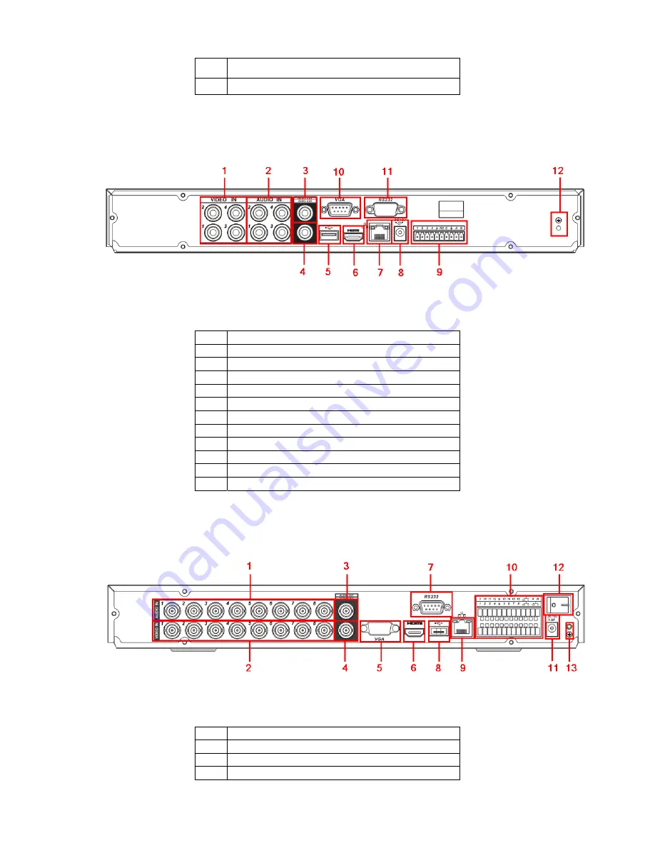
1.6.2.2 4-ch 2CIF Real-time Series  

This series DVR rear panel is shown as below. See Figure 1-13. 


Figure 1-13 

Please refer to the following sheet for detailed information. 

1 Video 

input 

Audio input  

3 Audio 

output 

4 Video 

output 

USB port   

6 HDMI 

port 

Network port   

8 Power 

socket 

Alarm input/alarm output/RS485 port 

10 

Video VGA output 

11 

RS232 port   

12 GND 

port 


1.6.2.3 8-ch 2CIF Real-time Series  

This series DVR rear panel is shown as below. See Figure 1-14. 


Figure 1-14 

Please refer to the following sheet for detailed information. 

1 Video 

input 

Audio input  

3 Audio 

output 

4 Video 

output 

Summary of Contents for N56 Series

Page 1: ...N56 Series DVR Quick Start Guide Version 1 2 2...

Page 2: ...Panel 12 1 6 1 Mini 1U Series 12 1 6 2 1U Series 15 1 6 3 1 5U Series 20 1 6 4 2U Series 20 1 7 Connection Sample 21 1 7 1 Mini 1U Series 21 1 7 2 1U Series 22 1 7 3 1 5U 23 1 7 4 2U 24 1 8 Alarm Inpu...

Page 3: ...38 2 5 5 Snapshot Disk For special series only 38 2 6 Network Setup 39 2 7 Pan Tilt Zoom 40 2 7 1 PTZ Setup 40 2 7 2 PTZ Operation 41 2 7 3 3D Intelligent Positioning Key 42 3 Web Client Operation 43...

Page 4: ...wards Handle with care Do not apply power to the DVR before completing installation Do not place objects on the DVR 4 Qualified engineers needed All the examination and repair work should be done by t...

Page 5: ...el and the ports in the rear panel please refer to the User s Manual included in the resource CD The model label in the front panel is very important please check according to your purchase order The...

Page 6: ...e with the clip and then place the upper cover back 8 Secure the screws in the rear panel and the side panel 1 Loosen the screws of the upper cover 2 Line up the HDD to the four holes of the HDD brack...

Page 7: ...Series The front panel of mini 1U series product is shown as in Figure 1 1 2 Remove the HDD upper bracket 5 Use screws to fix HDD 6 Install the upper bracket and then Use screws to fix HDD in the bra...

Page 8: ...p and down Increase decrease numeral Assistant function such as PTZ menu Up 1 Down 4 S T In text mode input number 1 4 English character G H I Shift current activated control Left 2 Right 3 W X When p...

Page 9: ...is button to reverse playback In reverse playback click this button to pause playback In text mode input number 6 English character M N O Play Next 9 f In playback mode playback the next video In menu...

Page 10: ...real time monitor mode Confirm current operation Go to default button Enter ENTER Go to menu One window monitor mode click this button to display assistant function PTZ control and image color Backsp...

Page 11: ...ft In textbox click this button to switch between numeral English Small Capitalized donation and etc Activate current control modify setup and then move up and down Increase decrease numeral Assistant...

Page 12: ...ode input number 6 English character M N O Play Next 9 f In playback mode playback the next video In menu setup go to down ward of the dropdown list In text mode input number 9 English character W X Y...

Page 13: ...A B C 3 English character D E F Go to previous menu or cancel current operation ESC ESC When playback click it to restore real time monitor mode Confirm current operation Go to default button Enter E...

Page 14: ...In pause mode click this button to resume playback In text mode input number 5 English character J K L USB port To connect USB storage device USB mouse Network abnormal indication light Net Network er...

Page 15: ...king with direction keys or numeral keys to select the recording channel Slow play Multiple slow play speeds or normal playback One window monitor mode click this button to display assistant function...

Page 16: ...mode turn the inner dial to realized frame by frame playback Only applies to some special versions USB port To connect USB storage device USB mouse Remote control indication light ACT Remote control i...

Page 17: ...el is shown as below See Figure 1 8 Figure 1 8 Please refer to the following sheet for detailed information 1 Video input 2 Audio input 3 Audio output 4 Video VGA output 5 On off button 6 Video output...

Page 18: ...put 13 On off button The rear panel of the 8 channel series product is shown as in Figure 1 10 Figure 1 10 Please refer to the following sheet for detailed information 1 Video input 2 Video output 3 A...

Page 19: ...9 USB port 10 Network port 11 RS 485 port 12 Power socket 13 GND port 1 6 2 1U Series 1 6 2 1 Full D1 Series The rear panel is shown as in Figure 1 12 Figure 1 12 Please refer to the following sheet...

Page 20: ...put 2 Audio input 3 Audio output 4 Video output 5 USB port 6 HDMI port 7 Network port 8 Power socket 9 Alarm input alarm output RS485 port 10 Video VGA output 11 RS232 port 12 GND port 1 6 2 3 8 ch 2C...

Page 21: ...5 Please refer to the following sheet for detailed information 1 Video input 2 1st to 4th channel audio input 3 Audio output 4 Video output 5 Video VGA output 6 HDMI port 7 RS232 port 8 USB port 9 Net...

Page 22: ...port 14 D sub port 5th to 16th channel audio input port 1 6 2 6 CIF Real time Series The 4 channel series DVR rear panel is shown as below See Figure 1 17 Figure 1 17 Please refer to the following she...

Page 23: ...rk port 9 RS485 port 10 Power socket 11 Alarm input Alarm output 12 On off button 13 GND port The 16 channel series DVR rear panel is shown as below See Figure 1 19 Figure 1 19 Please refer to the fol...

Page 24: ...atrix video output loop video output 6 Video input 7 Video CVBS output 8 Bidirectional talk output 9 Bidirectional talk input 10 Audio output 11 Alarm input Alarm output RS485 port 12 Video VGA output...

Page 25: ...idirectional talk output 14 Alarm input Alarm output RS485 port 15 Video VGA output 16 HDMI port 17 RS 232 port 18 eSATA port 19 USB port 20 Network port When connect the Ethernet port please use cros...

Page 26: ...22 Figure 1 22 1 7 2 1U Series Please refer to Figure 1 23 for connection sample Please note the following interface is based on the 2CIF real time series product...

Page 27: ...23 Figure 1 23 1 7 3 1 5U The connection sample is shown as in Figure 1 24 Please note the following figure is based on the 16 channel series product...

Page 28: ...24 Figure 1 24 1 7 4 2U The connection sample is shown as in Figure 1 25 Please note the following figure is based on the 16 channel series product...

Page 29: ...ely count the alarm input and out channel amount according to the ports on the rear panel There are two alarm input types for you to select normal open NO and normal close NC 1 8 1 Alarm Input and Out...

Page 30: ...Series The interface is shown as in Figure 1 27 Figure 1 27 Please refer to the following sheet and Figure 1 27 for detailed information Parameter Grounding Alarm GND Alarm Input 1 2 16 It becomes va...

Page 31: ...th cable 485 A B 485 communication port They are used to control devices such as PTZ Please parallel connect 120T between A B cables if there are too many PTZ decoders 1 8 1 4 1 5U Series You can refe...

Page 32: ...fer to the following sheet and Figure 1 32 for alarm input and output information Figure 1 32 In the first line from the left to the right 1 2 3 4 5 6 7 8 9 10 11 12 13 14 15 16 ALARM 1 to ALARM 16 Th...

Page 33: ...the Ground of the DVR and the ground of the alarm detector z Please connect the NC port of the alarm sensor to the DVR alarm input ALARM z Use the same ground with that of DVR if you use external pow...

Page 34: ...n See Figure 2 1 Figure 2 1 The system login interface is shown as in Figure 2 2 System consists of four accounts z Username admin Password admin administrator local and network z Username 888888 Pass...

Page 35: ...r the sub menu Figure 2 3 2 1 3 Logout There are two ways for you to log out The first one is from menu option In the main menu click shutdown button you can see an interface is shown as below See Fig...

Page 36: ...ify the channel name please refer to the display settings Main Menu Setting Display Preview Zoom Function Move your mouse to the left top corner of the preview interface you can see the preview zoom b...

Page 37: ...se there is no picture or file zIn any play mode click the date you want to see you can see the corresponding record file trace in the time bar 4 Playback mode and channel selection pane zPlayback mod...

Page 38: ...normal play mode when you pause current play you can click W and X to begin frame by frame playback In frame by frame playback mode click to restore normal playback Slow play In playback mode click it...

Page 39: ...n by default z The motion detect play stopped once you switch the play file z Operations such as set time bar click the play button or any file list operation will stop current motion detect play Othe...

Page 40: ...click save button system goes back to the previous menu At the bottom of the menu there are color bars for your reference Green color stands for regular recording yellow color stands for motion detect...

Page 41: ...alarm occurred z In Encode interface click snapshot button to input snapshot mode size quality and frequency z In General interface please input upload interval z In Detect interface please enable sn...

Page 42: ...hen click save button See Figure 2 11 Please refer to the User s Manual included in the resource CD for detailed information Please boot up corresponding FTP server Please enable schedule snapshot or...

Page 43: ...on See Figure 2 14 z IP address Here you can input IP address z DHCP It is auto search IP function When enable DHCP function you can not modify IP Subnet mask Gateway These values are from DHCP functi...

Page 44: ...s the downloaded data first if you enable this function The download speed is 1 5X or 2 0X of the normal speed After completing all the setups please click save button system goes back to the previous...

Page 45: ...ation In one window display mode right click mouse click Fn Button in the front panel or click Fn key in the remote control The interface is shown as in Figure 2 16 Figure 2 16 Click Pan Tilt Zoom the...

Page 46: ...e this function needs protocol supported and can only be operated by mouse Click this key system goes back to the single screen mode Drag the mouse in the screen to adjust section size It can realize...

Page 47: ...te the control or you can go to C Program Files webrec to delete Single folder z Current series product supports various browsers such as Safari firebox browser Google browser Device only support 1 ch...

Page 48: ...ee Figure 3 2 Click the channel name on the left side you can view the real time video Figure 3 2 3 3 2 WAN Login In WAN mode after you logged in the interface is shown as below See Figure 3 3 Figure...

Page 49: ...ments contained in products will not leak or mutate so that the use of these substances or elements will not result in any severe environmental pollution any bodily injury or damage to any assets The...

Reviews: