Dahua IPC-HF5541F-ZE-S3 Quick Start Manual Download Page 11

Quick Start Guide 

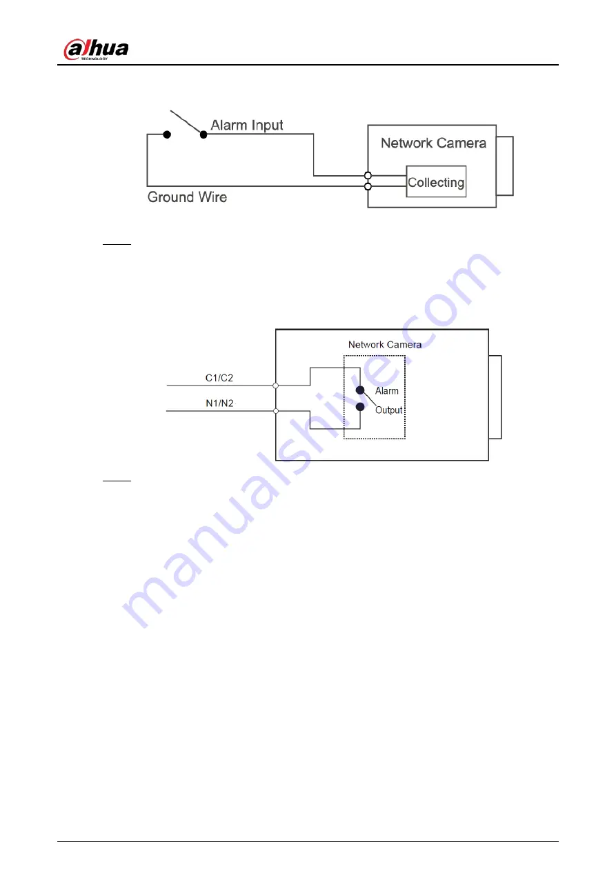
Figure 1-4 Alarm input 


Step 2 

Connect alarm output device to the alarm output end of the I/O port. The alarm output is 
relay switch output, which can only connect to OUT_GND alarm devices. 
N1 and C1 or N2 and C2 constitute a switch to provide the alarm output. 
The switch is normally open and closed when there is alarm output. 

Figure 1-5 Alarm output 


Step 3 

Log in to web page, and then configure alarm input and alarm output in alarm settings. 

  The alarm input on the web page is corresponding to the alarm input end of the I/O 

port. There will be high level and low level alarm signal generated by the alarm input 
device when alarm occurs. Set the input mode to "NO" (default) if the alarm input signal 
is logic "0" and to "NC" if the alarm input signal is logic "1". 

  The alarm output on the web page is corresponding to the alarm output end of the 

device, which is also the alarm output end of the I/O port. 

Summary of Contents for IPC-HF5541F-ZE-S3

Page 1: ...Box Network Camera Quick Start Guide ZHEJIANG DAHUA VISION TECHNOLOGY CO LTD V1 0 0...

Page 2: ...s which include but are not limited Providing clear and visible identification to inform people of the existence of the surveillance area and provide required contact information About the Manual The...

Page 3: ...be opened All trademarks registered trademarks and the company names in the manual are the properties of their respective owners Please visit our website contact the supplier or customer service if an...

Page 4: ...the local electrical safety code and standards and check whether the power supply is correct before operating the device Please follow the electrical requirements to power the device When selecting th...

Page 5: ...oint where they exit from the device Do not directly touch the photosensitive CMOS Use an air blower to clean the dust or dirt on the lens The dome cover is an optical component Do not directly touch...

Page 6: ...t use volatile solvents such as ethyl alcohol benzene diluent or abrasive detergents on the device to avoid damaging the coating and degrading the performance of the device The dome cover is an optica...

Page 7: ...ration 5 2 1 Initializing the Camera 5 2 2 Changing Device IP Address 7 2 3 Logging in to Web Page 8 3 Installation 9 3 1 Packing List 9 3 2 Dimensions 9 3 3 Installing the Camera 9 3 3 1 Installation...

Page 8: ...Quick Start Guide 1 1 Introduction 1 1 Structure Structure type might differ depending on different cameras Figure 1 1 Structure 1 Figure 1 2 Structure 2 Figure 1 3 Structure 3...

Page 9: ...on The Camera is recording Green light flashes The Camera detects wireless device Yellow light is solid on Green light Yellow light G GND Ground end of RS 232 serial port TX RS 232 port Sending end o...

Page 10: ...al from devices such as pick up Some cameras are only equipped with 1 channel audio input port AUDIO IN2 LAN OPT Network port MB optical fiber port LAN Connect to standard Ethernet cable and provide P...

Page 11: ...Alarm output Step 3 Log in to web page and then configure alarm input and alarm output in alarm settings The alarm input on the web page is corresponding to the alarm input end of the I O port There w...

Page 12: ...ly to connect the Camera to the network The following figures are for reference only 2 1 Initializing the Camera Step 1 Double click ConfigTool exe to open the tool Step 2 Click Modify IP Step 3 Click...

Page 13: ...lect one or several cameras in uninitialized status and then click Initialize Step 7 Select the cameras to be initialized and then click Initialize If you do not provide the linked information for pas...

Page 14: ...ne time This section is based on changing IP addresses in batches Changing IP addresses in batches is available only when the corresponding cameras have the same login password Step 1 Follow Step1 to...

Page 15: ...s from DHCP server when you select DHCP Step 4 Click OK 2 3 Logging in to Web Page Step 1 Open IE browser enter the IP address of the Camera in the address bar and then press the Enter key If the setu...

Page 16: ...h as electric drill is not provided in the package The operation manual and related tool information are contained in the disk or the QR code Figure 3 1 Packing list 3 2 Dimensions Figure 3 2 Dimensio...

Page 17: ...Install housing 3 3 3 Installing SD Card SD card slot is available on select models Disconnect the power before installing or removing the SD card Press the reset button for 10 seconds to reset the C...

Page 18: ...Figure 3 6 Install lens 3 3 5 Attaching the Camera Make sure that the mounting surface is strong enough to hold at least three times the weight of the Camera and bracket Figure 3 7 Cable going through...

Page 19: ...e mounting surface 3 3 6 Using I O Port Step 1 Use a tool like slotted screwdriver to press the I O button Step 2 Insert the I O port For details about I O port see Table 1 1 Step 3 Release the tool a...

Page 20: ...Quick Start Guide 13 3 3 7 Adjusting Lens Angle Figure 3 10 Adjust lens angle...

Page 21: ...Quick Start Guide...

Reviews: