10
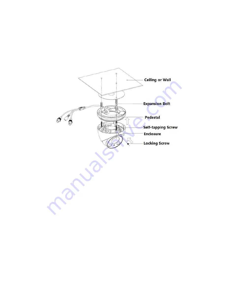
Model E: Insert the enclosure into the pedestal together with the dome body, turn the
locking screws clockwise and fix them preliminarily; rotate enclosure and dome body to a
proper monitoring location; finally tighten the locking screws to fix it completely.
So far, you have completed device installation and cable connection, you can check monitoring
picture via back-end coding device.
Please refer to the following installation steps if it is model F.
Step 1
Loosen the locking screw and take off the enclosure.
Step 2
Take out the installation position map from the accessories bag, paste it on the ceiling or wall
and dig holes on the installation surface according to the installation position map.
Step 3
Use tools to fix the expansion bolts into the installation holes.
Step 4
Adjust the pedestal location (pull the cable through side cable slot if it is side cable outlet).
Align the bolt fixing hole of device pedestal with the expansion bolt fixing holes of the
installation surface; insert the self-tapping screws into the expansion bolts and secure them
firmly to fix the pedestal on the installation surface (if it is top outlet, pull the cable through the
outlet hole on the installation surface after the pedestal is fixed firmly)
Step 5
Rotate the enclosure and dome body to a proper monitoring location; insert it into the pedestal
and tighten the locking screw.
Step 6
Connect the video output port of the device cable to the back-end coding device, and connect


