background image


22

2.7


Backup  

NVR support USB device backup and network download. Here we introduce USB backup. 
You can refer to User’s Manual Chapter 5 Web Operation for network download backup 
operation.  

a)  On the preview interface, right click mouse and then click main menu. 
b)  Click backup button, the interface is shown as below. See Figure 2-32. 


Figure 2-32 

c)  Select a backup device and then click Backup button. System pops up the following 

interface. See Figure 2-33. 

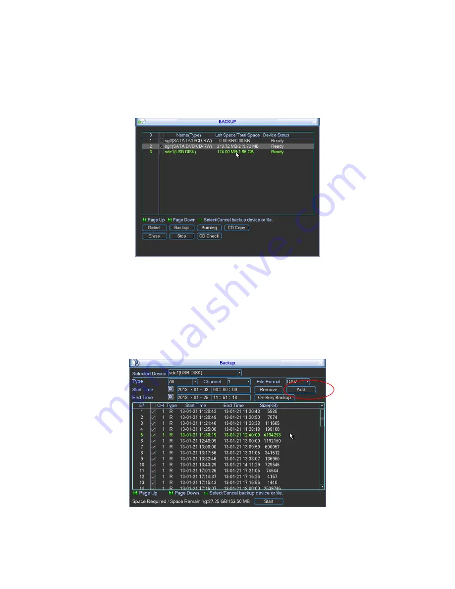
d)  Select backup device and then set channel, file start time and end time. Click add 

button, system begins search. All matched files are listed below. System automatically 
calculates the capacity needed and remained. 

Important 

If you want to backup PIP file, the channel shall be set as P. 


Figure 2-33 

Summary of Contents for Forensic NVR0404FD-S

Page 1: ...Forensic NVR Quick Start Guide Version 2 2 0 ...

Page 2: ... 1 8 1 Alarm Input and Output Details 4 1 8 2 Alarm Input Port 5 1 8 3 Alarm Output Port 5 2 Overview of Navigation and Controls 6 2 1 Login Logout Main Menu 6 2 1 1 Login 6 2 1 2 Main Menu 7 2 1 3 Logout 7 2 1 4 Auto Resume after Power Failure 8 2 2 Live Viewing 8 2 3 PTZ Control 9 2 4 PIP Setup 13 2 4 1 Video 1 4 PIP 13 2 4 2 4 window PIP mode 14 2 5 Real time Burning and CD Playback 15 2 6 Over...

Page 3: ... 23 2 9 CD Verification 23 3 Web Operation 26 3 1 Network Connection 26 3 2 Login 26 3 2 1 Real time Monitor 28 3 2 2 PTZ 30 3 2 3 Color 33 3 2 4 Picture Path and Record Path 33 Appendix Toxic or Hazardous Materials or Elements 35 ...

Page 4: ...pwards Handle with care Do not apply power to the NVR before completing installation Do not place objects on the NVR 4 Qualified engineers needed All the examination and repair work should be done by the qualified service engineers We are not liable for any problems caused by unauthorized modifications or attempted repair 5 Environment The NVR should be installed in a cool dry place away from dire...

Page 5: ...el please refer to the User s Manual included in the resource CD The model label in the front panel is very important please check according to your purchase order The label in the rear panel is very important too Usually we need you to represent the serial number when we provide the service after sales 1 3 After Remove the Chassis Please check the data cable power cable COM cable and main boar ca...

Page 6: ...Button Name Icon Function HDD record indicator light 1 4 The corresponding HDD is recording when it is on Network abnormal indicator light NET It is to alert you when network is abnormal or no connection 4 Unfasten the screws of the rear and side panel of the device 5 Use special data cable to connect the HDD cable and power cable 6 Place the bracket in line with the four holes of the device and t...

Page 7: ...D and etc 1 6 Rear Panel The series NVR rear panel is shown as below See Figure 1 2 Figure 1 2 Please refer to the following sheet for detailed information 1 Audio output 2 Video output 3 Network port 4 VGA output 5 RS232 port 6 HDMI port 7 USB port 8 eSATA port 9 Alarm input alarm output RS485 port 10 Line audio input port 11 Microphone port When connect the Ethernet port please use crossover cab...

Page 8: ...o the following sheet for alarm input and output information 1 2 3 4 ALARM 1 to ALARM 4 The alarm becomes active in low voltage NO1 C1 NO2 C2 There are two groups of normal open activation output on off button Earth cable 485 A B 485 communication port They are used to control devices such as PTZ Please parallel connect 120TΩ between A B cables if there are too many PTZ decoders AB cable connectio...

Page 9: ...t the Ground of the NVR and the ground of the alarm detector z Please connect the NC port of the alarm sensor to the NVR alarm input ALARM z Use the same ground with that of NVR if you use external power to the alarm device Figure 1 5 1 8 3 Alarm Output Port z Provide external power to external alarm device z To avoid overloading please read relay parameters sheet in the User s Manual carefully z ...

Page 10: ... information See Figure 2 1 Figure 2 1 The system login interface is shown as in Figure 2 2 System consists of four accounts z Username admin Password admin administrator local and network z Username 888888 Password 888888 administrator local only z Username 666666 Password 666666 Lower authority user who can only monitor playback backup and etc z Username default Password default hidden user You ...

Page 11: ...vice advanced and shutdown You can move the cursor to highlight the icon and then double click mouse to enter the sub menu Figure 2 3 2 1 3 Logout There are two ways for you to log out The first one is from menu option In the main menu click shutdown button you can see an interface is shown as below See Figure 2 4 Figure 2 4 There are several options for you See Figure 2 5 ...

Page 12: ...w there is a volume bar at the right bottom corner The volume bar becomes red when it is the max value Right click mouse you can see system pops up the following menu See Figure 2 6 Please refer to the following sheet for detailed information Name Function View 1 System displays in one channel You can select channel 1 to channel 4 View 4 System displays in 4 window View PIP System displays in pict...

Page 13: ...click AUX key in the remote control Click Pan Tilt Zoom the interface is shown as below See Figure 2 7 Here you can set the following items z Step value ranges fro 1 to 8 z Zoom z Focus z Iris Please click icon and to adjust zoom focus and iris Figure 2 7 In Figure 2 7 please click direction arrows See Figure 2 8 to adjust PTZ position There are total 8 direction arrows Figure 2 8 3D Intelligent P...

Page 14: ...d the higher the speed Figure 2 9 Here is a sheet for you reference Name Function key function Shortcut key Function key function Shortcut Key Zoom Near Far Focus Near _ Far Iris close W Open f Preset Patrol Pattern Scan In Figure 2 7 please click the set button The interface is shown as below See Figure 2 10 Here you can set the following items z Preset z Tour z Pattern z Border Figure 2 10 In X3...

Page 15: ...t Setup In Figure 2 7 use eight direction arrows to adjust camera to the proper position In Figure 2 10 click preset button and input preset number The interface is shown as in Figure 2 12 Now you can add this preset to one tour Figure 2 12 Activate Preset In Figure 2 11 please input preset number in the No blank and click preset button Patrol setup Tour Setup In Figure 4 38 click patrol button Th...

Page 16: ... click border button The interface is shown as in X348H348H348H Figure 4 43 Please go to X349H349H349H X349H349H349HFigure 4 35 use direction arrows to select camera left limit Then please go to X350H350H350H Figure 4 43X and click left limit button Repeat the above procedures to set right limit Figure 2 15 Activate Auto Scan In Figure 2 11 click Auto Scan button the system begins auto scan Corres...

Page 17: ...tton to go to or exit speed dome menu Click Page Switch button system goes back to Figure 2 7 Figure 2 17 2 4 PIP Setup 2 4 1 Video 1 4 PIP You can view different channels on the PIP mode You can follow the steps listed below a From main menu setting general check the navigation bar to enable navigation function Close general interface and then left click mouse on the preview interface you can see...

Page 18: ...he white channel is the PIP channel and black channel is the current selected channel z On the PIP mode the volume bar is the mixed audio For mode 1 to mode 4 system can mix the audio of the main interface and the PIP interface It is the audio of the PIP preview and record audio 2 4 2 4 window PIP mode You can view 4 window on the PIP mode You can follow the steps listed below a From main menu set...

Page 19: ...he preview interface that is to say it is the audio of the channel P on the PIP mode z You can use mouse to drag the PIP picture to the proper position and drag mouse to zoom in or zoom out 2 5 Real time Burning and CD Playback This series product can burn real time video to the CD for future reference You can click the REC STOP at the front panel to start or stop burning Or you can go to the burn...

Page 20: ...ord channel c Now you can set burn setup mark setup and etc Please note you can not set during the burning process Click Settings button you can see the following interface See Figure 2 23 Here you can set interrogation time and resolution Click Save button System can calculate the corresponding channel bit stream according to you input information and the CD space Figure 2 23 Click Burn setup sys...

Page 21: ... process you can click it to replace CD manually System pops up current CD and then you can input a new one System begins burning data from the previous 5 minutes of the previous CD so that there is no missing data between these two CDs z Pause During the burning process you can pause current burning if the court is adjournment Click continue button you can begin burning again and all data is on t...

Page 22: ...perature and humidity device you need to set corresponding parameters so that you can overlay temperature humidity information on the monitor video or record file You can connect the temperature humidity device via the RS232 2 6 1 RS232 Mode a Set COM protocol On the preview interface right click mouse and then select main menu from main menu advanced card overlay The interface is shown as in Figu...

Page 23: ...om the dropdown list and then click overlay setup button you can see the following interface See Figure 2 28 Check the preview or monitor mode after T H Temperature humidity and then click Set button to set overlay position Click Save button to exit Figure 2 28 Tips z In Figure 2 28 click Set button you can set overlay position z Each channel can set its own overlay information The channel 1 4 enc...

Page 24: ...y output shall go through a RS485 232 tool so that you can connect the RS232 to the RS232 port of the device z For some series RS485 232 tool it may need power supplying Otherwise the data may not stable or there is no data at all In this situation device can not overlay information 2 6 2 RS485 Mode a Set COM protocol On the preview interface right click mouse and then select main menu from main m...

Page 25: ...u need to select channel P PIP to overlay information z Preview means you can overlay temperature humidity information on local preview window Monitor means you can overly temperature humidity information on the record file so that you can view it when playback b Connect temperature humidity device to the NVR Connect the A2 and Y2 cable at the rear panel of the NVR to the A or cable of the tempera...

Page 26: ...p button the interface is shown as below See Figure 2 32 Figure 2 32 c Select a backup device and then click Backup button System pops up the following interface See Figure 2 33 d Select backup device and then set channel file start time and end time Click add button system begins search All matched files are listed below System automatically calculates the capacity needed and remained Important I...

Page 27: ...the preview interface right click mouse and then click main menu Click backup button you can go to backup interface Click CD copy button at the bottom of the interface You can go to the following interface See Figure 2 34 You can see some reference information at the right bottom corner of the interface You can see the corresponding dialogue box after the copy operation Figure 2 34 Note z During t...

Page 28: ...k mouse and then select main menu Click Backup button Check CD Check button You can see CD check interface shown as below See Figure 2 36 Figure 2 36 Select a CD from the dropdown list at the bottom of the interface and then check the file s you want to verify Now system automatically begins check operation You can see the check result on the right column System displays as success if the file is ...

Page 29: ...25 Figure 2 37 ...

Page 30: ...he new version can overwrite the previous one z If you want to un install the web control please run uninstall webrec2 0 bat Or you can go to C Program Files webrec to remove single folder Please note before you un install please close all web pages otherwise the un installation might result in error 3 2 Login Open IE and input NVR address in the address column For example if your NVR IP is 10 10 ...

Page 31: ...e LAN and WAN Note For security reasons please modify your password after you first login Figure 3 3 After you logged in you can see the main window See Figure 3 6 This main window can be divided into the following sections z Section 1 there are five function buttons configuration search alarm about log out z Section 2 there are channel number and three function buttons start dialog and local play...

Page 32: ...indow 6 window 8 window 9 window 13 window 16 window 20 window 25 window 36 window See Figure 3 4 Figure 3 4 Preview window switch System support 1 4 8 9 16 window real time preview Please you need to have the proper rights to implement preview operation You can not preview if you have no right to preview the either channel See Figure 3 5 Please note this series device does not support this functi...

Page 33: ...When you click local record button the system begins recording and this button becomes highlighted You can go to system folder RecordDownload to view the recorded file z 4 Capture picture You can snapshoot important video All images are memorized in system client folder download picture default z 5 Audio Turn on or off audio It has no relationship with system audio setup z 6 Close video Please ref...

Page 34: ...nal talk process system will not encode the audio data from the 1 channel Local Play The Web can playback the saved Extension name is dav files in the PC end Click local play button system pops up the following interface for you to select local play file See Figure 3 10 Figure 3 10 3 2 2 PTZ Before PTZ operation please make sure you have properly set PTZ protocol Please refer to User s Manual Sett...

Page 35: ...ust section size It can realize PTZ automatically 3 2 2 2 Speed System supports eight level speed You can select from the dropdown list Speed 2 is faster than speed 1 3 2 2 3 Zoom Focus Iris Here is a sheet for you reference Name Function key Function Function key Function Zoom Near Far Focus Near Far Iris close Open In Figure 3 11 click PTZ setup button you can see the following interface See Fig...

Page 36: ...n Figure 3 12 move the camera to your desired location and then input preset value Click add button you have set one preset 3 2 2 7 Auto tour In Figure 3 12 input auto tour value and preset value Click add button you have added one preset in the tour Repeat the above procedures you can add more presets in one tour 3 2 2 8 Assistant You can select the assistant item from the dropdown list See Figur...

Page 37: ...order becomes green Or you can click default button to use system default setup Figure 3 14 3 2 4 Picture Path and Record Path Click more button in Figure 3 14 you can see an interface is shown as in Figure 3 15 Figure 3 15 Click the record item you can see there are two options DAV ASF Click picture path button you can see an interface is shown as in Figure 3 16 Please click choose button to modi...

Page 38: ...boot button system pops up the following dialogue box See Figure 3 18 Please click OK to reboot Figure 3 18 If there is local use logged in the system menu or the Web logged in user has no right to reboot the device system pops up a dialogue box to alert you For detailed operation information please refer to the User s Manual included in the resources CD ...

Page 39: ...ements contained in products will not leak or mutate so that the use of these substances or elements will not result in any severe environmental pollution any bodily injury or damage to any assets The consumer is not authorized to process such kind of substances or elements please return to the corresponding local authorities to process according to your local government statutes Note z For detail...

Reviews: