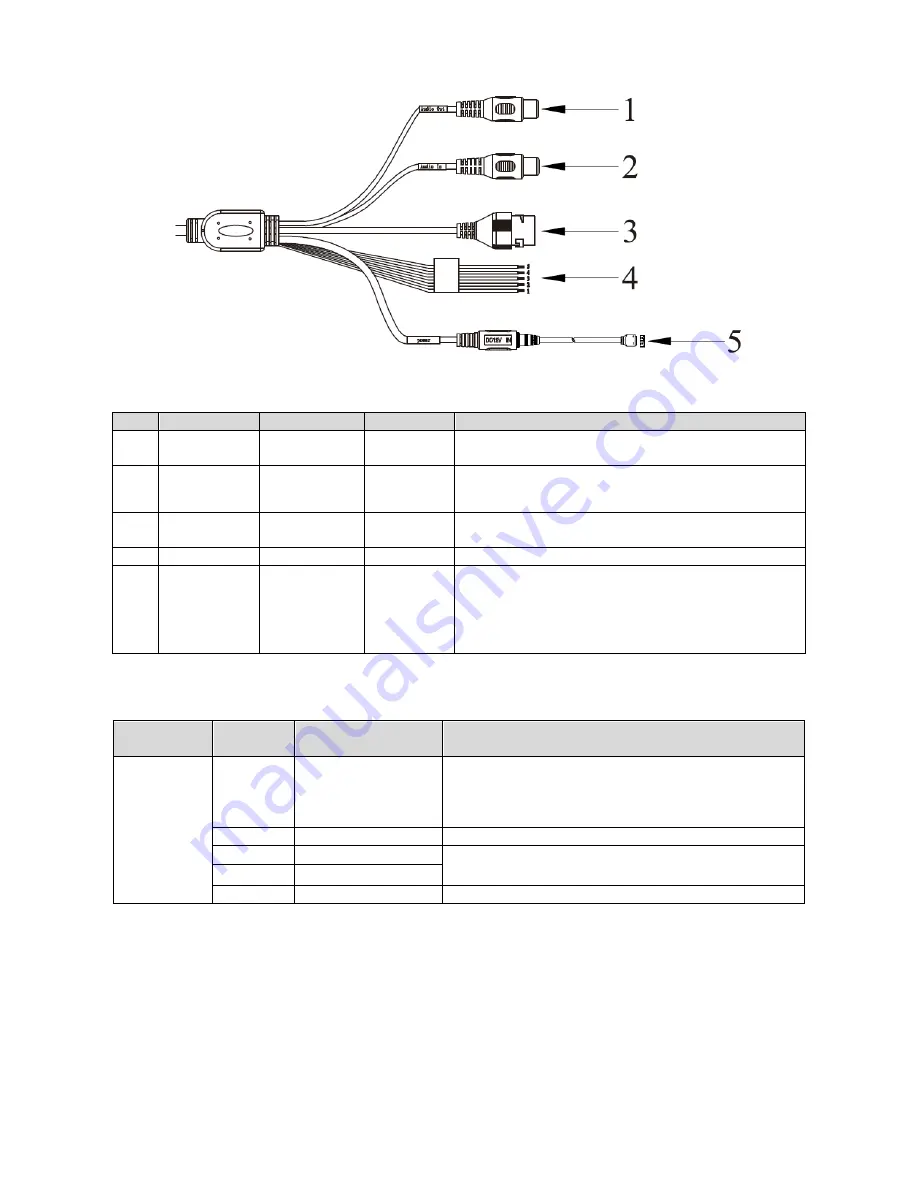
5
Figure 2-5
No.
Port
Function
Connector
Description
1
AUDIO OUT
Audio output
port
RCA
Reserved
2
AUDIO IN
Audio input
port
RCA
Reserved
3
LAN
Ethernet port
Ethernet
port
Connect to standard Ethernet, provide PoE power.
4
I/O
I/O port
-
Alarm signal input, output. See Chart 2-2.
5
Power
Power input
port
-
Input DC 12V
,
power supply must follow device
label.
Warning:
If you do not follow device label for power
supply, the device may be damaged.
Chart 2-1
Interface
Name
No.
Port Name
Description
I/O Port
1
ALARM_OUT
Alarm output interface, output alarm signal link
to open barrier.
NO
:
NO alarm output.
Used with ALARM_OUT_GND end.
2
ALARM_OUT_GND Alarm output puclic
3
ALARM_IN1
2-ch IO output
(
receive external alarm source
switch signal
)
, used to trigger snapshot.
4
ALARM_IN2
5
ALARM_IN_GND
Grounding
Chart 2-2
2.3.2 Rear Panel
Note:
Rear panel structure is for ITC237-PU1B-IR, ITC237-PU1B-L.
Structure figure is for reference only.


