background image


2  Device Installation  

2.1  Lens Installation 


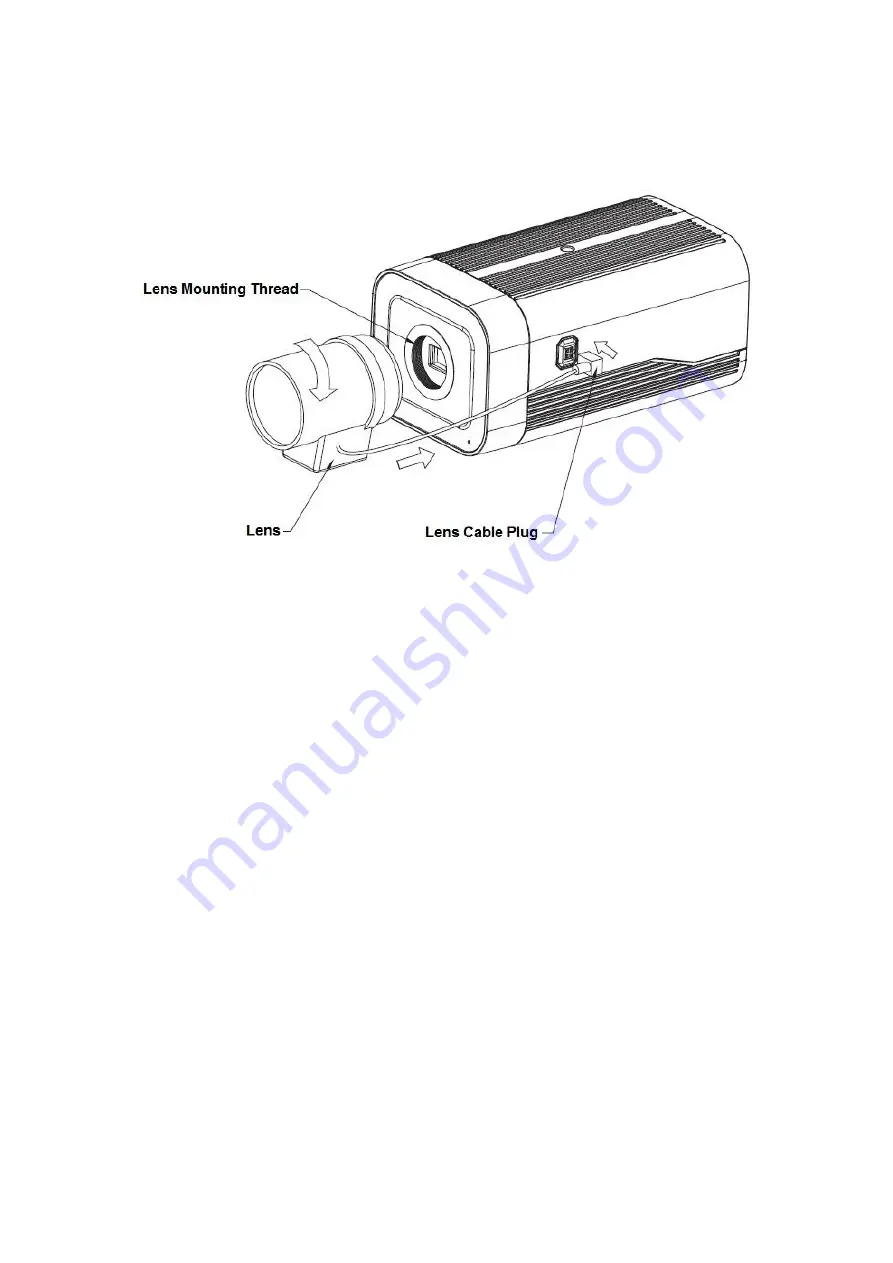
Figure 2-1 


2.1.1  Auto Iris Lens Installation  

Step 1  

Remove the CCD protection cover on the device, aim the lens at the lens installation position, 

and turn the lens clockwise until it is installed firmly.  

Step 2  

Insert the lens cable plug into the connector of auto iris lens on the camera side panel.  

Step 3  

Make the image clear via adjusting focal length.  


2.1.2   Manual Iris Lens Installation  

Please follow the steps listed below for auto aperture lens installation.  

Step 1  

Remove the CCD protection cover of the device, 

Step 2  

Install the C/CS adapter ring on the camera; turn clockwise to the end to cling to the focusing ring 

on the camera closely. (Only C lens needs to install adapter ring) 

Step 3  

 Aim the C port lens at the lens installation position of the C/CS adapter ring (aim the CS port 

lens at the lens installation position of the camera focusing ring); turn the lens clockwise until it is 

firmly installed.  

Step 4  

Use slotted screwdriver to unfasten the screw near the focusing ring and then turn counter 

clockwise to move the focusing ring out for several millimeters.  Now you can focus manually and 
check the video is clear or not. If you can’t see the clear video, you can adjust back focus. 

Summary of Contents for DH-IPC-HF8835F

Page 1: ...Dahua HD Box Network Camera Quick Start Guide Version 1 0 0 Zhejiang Dahua Vision Technology Co LTD ...

Page 2: ...he same time it may result in device damage We assume no liability or responsibility for all the fires or electrical shock caused by improper handling or installation We are not liable for any problems caused by unauthorized modification or attempted repair 2 Environment Please don t aim the device at strong light such as lighting sunlight and so on to focus otherwise it may cause overexposure It ...

Page 3: ...tergent with abrasiveness otherwise it will damage the surface coating or reduce the working performance of the device Dome cover is an optical device please don t touch or wipe cover surface directly during installation and use please refer to the following methods to deal with once dirt is found Stained with dirt Use oil free soft brush or hair dries to remove it gently Stained with grease or fi...

Page 4: ...provide reasonable protection against harmful interference This equipment generates uses and can radiate radio frequency energy and if not installed and used in accordance with the instruction manual may cause harmful interference to radio communication However there is no guarantee that interference will not occur in a particular installation If this equipment does cause harmful interference to r...

Page 5: ...l talk 3 1 4 Alarm Setup 4 1 4 1 Alarm Input and Output Connection 4 2 Device Installation 6 2 1 Lens Installation 6 2 1 1 Auto Iris Lens Installation 6 2 1 2 Manual Iris Lens Installation 6 2 2 I O Port Application 7 3 Network Configuration 8 3 1 Modify IP Address 8 3 2 Login WEB Interface 9 ...

Page 6: ...OUT Video output port Output analog video signal It can connect to TV monitor to check image It can preview image via the DVR which supports HDCVI when it outputs HDCVI signal AC 24V DC 12V Power port Able to input 12V DC or AC 24V power supply and support power supply at the same time Indicator Light Red light System boots up red light is normally on System upgrades red light flashes System reset...

Page 7: ...y open alarm output end C1 C2 Alarm output public end Note N1 can only be used with C1 while N2 can only be used with C2 when connecting alarm device C1 N2 C2 P Power foldback output port It outputs DC 12V power P connects to positive pole while G connects to negative pole G adjacent to P RESET RESET button Restore device factory default setup When system is running normally press the RESET button...

Page 8: ...for reference only which is used to know the device dimension please refer to the actual device for more details The unit is mm See Figure 1 2 Figure 1 2 1 3 Bidirectional talk Note Some products do not support bidirectional talk which cannot be applied to this chapter It is not allowed to use on site listening when the device is applying bidirectional talk Step 1 Connect the speaker or the MIC to...

Page 9: ...larm input device to the IN alarm input port on the rear panel I O port Step 2 Connect the alarm output device to the N1 and C1 or N2 or C2 NO of I O port on the rear panel The alarm output port supports NO normally open alarm device only Step 3 Open the Web go to the Figure 1 3 Here you can make the alarm input setup and alarm output setup Here the alarm input is the alarm input on the correspond...

Page 10: ...V or it is idle the device collects the logic 1 When the input signal is grounded the device collects the logic 0 Figure 1 4 Please refer to the following figure for alarm output information See Figure 1 5 Alarm output N1 and C1 or N2 and C2 make up a switch to provide the alarm output Generally the switch is on and it will be off when there is an alarm output Figure 1 5 ...

Page 11: ...ove the CCD protection cover of the device Step 2 Install the C CS adapter ring on the camera turn clockwise to the end to cling to the focusing ring on the camera closely Only C lens needs to install adapter ring Step 3 Aim the C port lens at the lens installation position of the C CS adapter ring aim the CS port lens at the lens installation position of the camera focusing ring turn the lens clo...

Page 12: ...ing ring Now the installation completed 2 2 I O Port Application Figure 2 2 Install Cable Step 1 Use the small slotted screwdriver to press the corresponding button of cable groove Step 2 Insert the cable into the groove Step 3 Release the screwdriver which presses the groove button and complete cable installation ...

Page 13: ... approach of modifying IP address via Quick Configuration Tool also you can modify the IP address in the network parameters of the WEB interface please refer to the document in the disk WEB Operation Manual for more details Note Currently the quick configuration tool only supports the cameras which apply to the same network segment with computer IP address Step 1 Double click the ConfigTools exe a...

Page 14: ...aces the figures below are just for reference please refer to the document WEB Operation Manual in the disk and the actual interface for more details Step 1 Open IE and input the modified camera IP address in the address bar Step 2 The login interface is shown below please input your user name and password Default user name is admin and password is admin respectively click login See Figure 3 3 for...

Page 15: ...re 3 3 Step 3 Install controls according to the system prompt see Figure 3 4 for the WEB main interface Please modify the administrator password as soon as possible after you successfully logged in Figure 3 4 ...

Page 16: ...e If there is any uncertainty or controversy please refer to the final explanation of us Please visit our website or contact your local service engineer for more information Zhejiang Dahua Vision Technology Co Ltd Address No 1199 Bin an Road Binjiang District Hangzhou PRC Postcode 310053 Tel 86 571 87688883 Fax 86 571 87688815 Email overseas dahuatech com Website www dahuasecurity com ...

Reviews: