background image


Installation Guide  10 

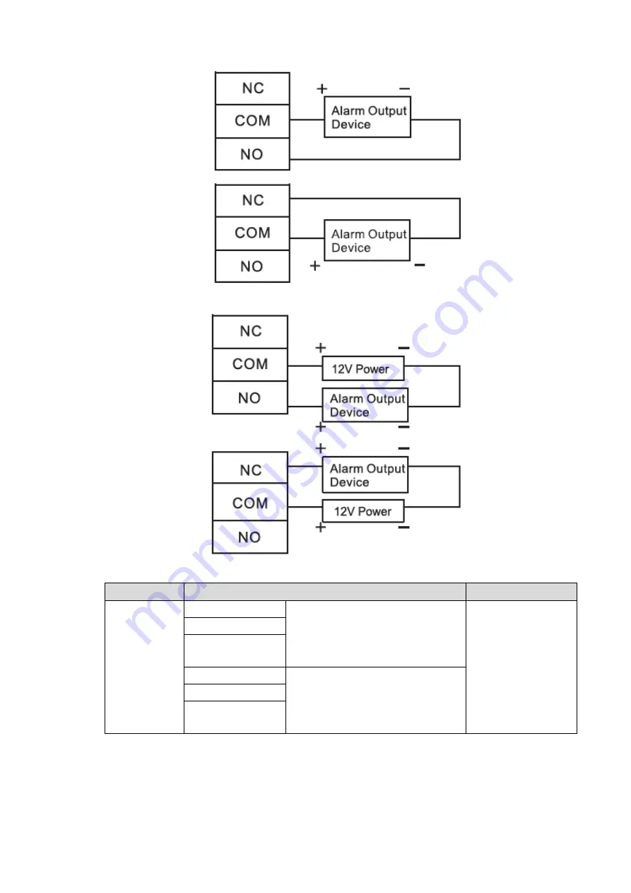
Figure 2-12  


Figure 2-13  


Table 2-7  

Port   

Wiring Terminal 

Description


Internal 

alarm output 

NC3 


Tamper alarm output of door 

1 entry reader and exit reader 


Timeout and intrusion alarm 

output of door 1 

Internal alarm 

output ports are 

able to connect 

audible and visual 

sirens. 

COM3 

NO3 

NC4 


Tamper alarm output of door 

2 entry reader and exit reader 


Timeout and intrusion alarm 

output of door 2 

COM4 

NO4 

2.3.8 Description of Alarm Input and Output Rule 

In case of alarm event, access controller can control the access and external alarm status. 

Please refer to Table 2-8 for detailed alarm input and output rules. 

Summary of Contents for ASC1202C-D

Page 1: ...Two door Two way Access Controller User s Manual V1 0 0 ...

Page 2: ...egularly change the credentials to your devices to help ensure that only authorized users are able to access the system 2 Change Default HTTP and TCP Ports Change default HTTP and TCP ports for systems These are the two ports used to communicate and to view video feeds remotely These ports can be changed to any set of numbers between 1025 65535 Avoiding the default ports reduces the risk of outsid...

Page 3: ...tem is set up for multiple users ensure that each user only has rights to features and functions they need to use to perform their job 10 UPnP UPnP will automatically try to forward ports in your router or modem Normally this would be a good thing However if your system automatically forwards the ports and you leave the credentials defaulted you may end up with unwanted visitors If you manually fo...

Page 4: ...eras to the PoE Ports on the Back of an NVR Cameras connected to the PoE ports on the back of an NVR are isolated from the outside world and cannot be accessed directly 16 Isolate NVR and IP Camera Network The network your NVR and IP camera resides on should not be the same network as your public computer network This will prevent any visitors or unwanted guests from getting access to the same net...

Page 5: ...hese limits are designed to provide reasonable protection against harmful interference in a commercial environment Operation of this equipment in a residential area is likely to cause harmful interference in which case the user will be required to correct the interference at his own expense For class B device these limits are designed to provide reasonable protection against harmful interference i...

Page 6: ...might collect personal data of others such as face fingerprints car plate number Email address phone number GPS and so on You need to be in compliance with the local privacy protection laws and regulations to protect the legitimate rights and interests of other people by implementing measures include but not limited to providing clear and visible identification to inform data subject the existence...

Page 7: ...rations description or errors in print If there is any doubt or dispute please refer to our final explanation Upgrade the reader software or try other mainstream reader software if the Guide in PDF format cannot be opened All trademarks registered trademarks and the company names in the Manual are the properties of their respective owners Please visit our website contact the supplier or customer s...

Page 8: ...put range Please don t dismantle the device arbitrarily Please transport use and store the device within allowed humidity and temperature range Power Requirement Please make sure to use batteries according to requirements otherwise it may result in fire explosion or burning risks of batteries To replace batteries only the same type of batteries can be used The product shall use electric cables pow...

Page 9: ...ription of Alarm Input and Output Rule 10 2 4 DIP Switch 11 2 5 Restart 12 3 Smart PSS Config 13 3 1 Login Client 13 3 2 Add Access Controller 13 3 2 1 Auto Search 13 3 2 2 Manual Add 15 3 3 Add User 17 3 3 1 Card Type 18 3 3 2 Single Add 19 3 4 Add Door Group 21 3 5 Authorize 23 3 5 1 Authorize According to Door Group 23 3 5 2 Authorize According to User 25 4 FAQ 27 1 Question After power on powe...

Page 10: ...Table of Contents IX 7 Question Online upgrade of the device 27 8 Question Max wiring distance and transmission distance of card reader and controller 27 5 Technical Parameters 28 ...

Page 11: ...2 door contact 2 tamper alarm 1 and intrusion alarm 4 Support 6 groups of control output electric lock 2 external alarm output 2 and internal alarm output 2 With RS485 port it may extend to connect control module FLASH storage capacity is 16M which may extend to 32M Support max 100 000 card holders and 150 000 card reading records Support tamper alarm illegal intrusion alarm unlock timeout alarm d...

Page 12: ...Overview 2 Figure 1 1 ...

Page 13: ...ide 2 1 System Structure System structure of two door two way access controller door lock and reader is shown in Figure 2 1 Figure 2 1 2 2 Device Installation Device installation diagram is shown in Figure 2 2 and Figure 2 3 The unit is mm ...

Page 14: ...tal weight of the device bracket and accessories Step 1 Measure every hole distance and position according to holes at rear shell of the device as shown in Figure 2 3 drill holes in the wall according to the measured positions Step 2 Embed expansion nuts and fix screws into the wall Step 3 Hang the whole device onto the screws ...

Page 15: ...In case of alarm input trigger external alarm output device to give an alarm Device wiring diagram is shown in Figure 2 4 Figure 2 4 2 3 2 Wiring Description of Exit Button Door Contact Corresponding wiring terminals of exit button and door contact are shown in Figure 2 5 Please refer to Table 2 1 for descriptions of wiring terminals ...

Page 16: ...button of door 2 GND Shared by exit button of door 2 and door contact input of door 2 SR2 Door contact input of door 2 2 3 3 Wiring Description of Lock Support 2 groups of lock control outputs serial numbers after the terminals represent corresponding doors Please choose a proper connection mode according to lock type as shown in Figure 2 6 Figure 2 7 and Figure 2 8 Please refer to Table 2 2 for d...

Page 17: ...orts to connect one type of reader 485 or Wiegand Please refer to Table 2 3 for descriptions of wiring terminals corresponding to readers Take door 1 for example other readers are the same Please refer to Table 2 4 for descriptions of reader cable specification and length Table 2 3 Port Wiring Terminal Cable Color Description Entry Reader of Door 1 485 Purple 485 reader 485 Yellow LED Brown Wiegan...

Page 18: ...ring Terminal Description External alarm input ALM1 Alarm input port 1 External alarm input ports are able to connect smoke detector and IR detector etc External alarm can link door open and closed status ALARM1 ALARM2 external alarm links all doors to be normally open ALARM3 ALARM4 external alarm links all doors to be normally closed GND Shared by alarm input port 1 and 2 ALM2 Alarm input port 2 ...

Page 19: ...T1 OUT2 ALM3 ALM4 triggers alarm output OUT2 2 3 7 Wiring Description of Internal Alarm Output With 2 ch internal alarm output after internal alarm input such as door timeout triggers an alarm the alarm output device gives an alarm for 15s During connection of alarm output device please select NC NO according to normally closed or normally open status NC represents normally closed status NO repres...

Page 20: ...door 1 Internal alarm output ports are able to connect audible and visual sirens COM3 NO3 NC4 Tamper alarm output of door 2 entry reader and exit reader Timeout and intrusion alarm output of door 2 COM4 NO4 2 3 8 Description of Alarm Input and Output Rule In case of alarm event access controller can control the access and external alarm status Please refer to Table 2 8 for detailed alarm input and...

Page 21: ...rusion alarm or unlock timeout alarm of no 1 door SR1 OUT1 No 1 alarm gives an alarm Intrusion alarm or unlock timeout alarm of no 2 door SR2 OUT2 No 2 alarm gives an alarm Tamper alarm of no 1 door reader RS 485 CASE OUT1 No 1 alarm gives an alarm Tamper alarm of no 2 door reader RS 485 CASE OUT2 No 2 alarm gives an alarm 2 4 DIP Switch Operate with DIP switch Figure 2 14 the switch is at ON posi...

Page 22: ...e others are 0 After restart the system restores factory defaults but user info is retained 2 5 Restart Press restart button as shown in Figure 2 4 to restart the device Restart button is to restart the device rather than modifying configuration ...

Page 23: ...aces for different versions Please refer to actual interface 3 1 Login Client Install the matching Smart PSS client and double click to run Carry out initialization configuration according to interface prompts and complete login 3 2 Add Access Controller Add access controller in Smart PSS select Auto Search and Add 3 2 1 Auto Search Devices are required to be in the same network segment Step 1 In ...

Page 24: ...ecific operations please refer to User s Manual of Smart PSS Client Step 3 Select the device that needs to be added and click Add The system pops up Prompt Step 4 Click OK The system displays Login Information dialogue box as shown in Figure 3 3 Figure 3 3 Step 5 Input User Name and Password to log in the device and click OK The system displays the added device list as shown in Figure 3 4 Please r...

Page 25: ...me port user name and password Alternatively double click the device to enter Modify Device interface Click this icon to enter Device Config interface and configure device camera network event storage and system info and When the device is online the icon is Click this icon to exit login and this icon turns to When the device is offline the icon is Click this icon to login with correct device info...

Page 26: ...77 Please fill in according to actual conditions Group Name Select the group of the device User Name and Password User name and password of the device Step 3 Click Add to add a device The system displays the added device list as shown in Figure 3 4 Please refer to Table 3 1 for details Doors of the added controller are displayed under Access tab as shown in Figure 3 7 To add more devices click Sav...

Page 27: ...Smart PSS Config 17 Figure 3 7 3 3 Add User Add users and bind with cards so as to distribute authority In New interface click Access to enter Access interface and complete access config here ...

Page 28: ...g 18 Figure 3 8 3 3 1 Card Type Card type shall be the same with card issuer otherwise it fails to read card number In Access interface click and then click to set the card type as shown in Figure 3 9 and Figure 3 10 ...

Page 29: ...igure 3 9 Figure 3 10 3 3 2 Single Add Add a single user send a card and input user info Step 1 In Access interface click and then click as shown in Figure 3 11 The system pops up Add User dialog box as shown in Figure 3 12 ...

Page 30: ...Smart PSS Config 20 Figure 3 11 Figure 3 12 Step 2 Add user info manually including basic info fingerprint info and details Please refer to Table 3 3 for details ...

Page 31: ...se it only applies to guest card Valid Time set the valid time of card which is 10 years by default Picture user picture max 120K Card no and user ID cannot be repeated Fingerprint Info Collect fingerprints with fingerprint reader and access reader Max 2 fingerprints for every person Support to enter fingerprint name Details Fill in detailed user info according to interface parameters Step 3 Click...

Page 32: ...Smart PSS Config 22 Figure 3 13 Step 2 Click Add The system pops up Add Door Group dialog box as shown in Figure 3 14 ...

Page 33: ...ng 3 5 Authorize Grant users authorities according to door group and user 3 5 1 Authorize According to Door Group Select a door group add corresponding users to the group so all users in the group obtain authority of all doors in the group Step 1 In Access interface click and then click Access Level as shown in Figure 3 15 ...

Page 34: ...art PSS Config 24 Figure 3 15 Step 2 Click The system pops up User Select dialog box Step 3 Select the user s department from dropdown list or enter the user s ID or name directly as shown in Figure 3 16 ...

Page 35: ...ization The search list filters user info without card number In the user list cancel the added user and delete the user s authority 3 5 2 Authorize According to User Select a user distribute door group and grant door group authority to the user Step 1 In Access interface click and then click User Right as shown in Figure 3 17 ...

Page 36: ...Smart PSS Config 26 Figure 3 17 Step 2 Click The system pops up Select Door Group dialog box as shown in Figure 3 18 Figure 3 18 Step 3 Select the door group and click OK to finish authorization ...

Page 37: ...tect the device Answer Please check whether TCP IP connector is connected properly and whether device IP is in the same network segment 4 Question After swiping card it prompts that card is invalid Answer Please check whether this card number has been added in the controller 5 Question Default IP of access controller Answer Default IP address is 192 168 0 2 6 Question Default port initial user nam...

Page 38: ...ted voltage 10V 15V DC rated current 0 75A Period 128 Holiday 128 Unlocking mode Card card password password card or password card fingerprint fingerprint password fingerprint or card or password by period Cross segment networking Support Two door interlocking Support One door two way card swiping Support Real time surveillance Support Fire alarm linkage Support Tamper alarm Support Intrusion alar...

Reviews: