background image

17 

Table 3-5 Wiegand output 

Parameter 

Description 

Wiegand output type 

The 

Wiegand

 output type determines the card number or the digit of 

the number than can be recognized by the standalone. 


Wiegand26, three bytes, six digits. 


Wiegand34, four bytes, eight digits. 


Wiegand66, eight bytes, sixteen digits. 

Pulse Width 

You can set pulse width and pulse interval. 

Pulse Interval 

Output Data Type 

You can select the types of output data. 


User ID: If User ID is selected, and then user ID will be output. 


Card No.: If Card No. is selected, and then card number will be 

output. 

3.8.3 TCP Port 

The range is 1025-65535, and it  is 37777 by default.  If you modify the port, the system will 

restart automatically. 

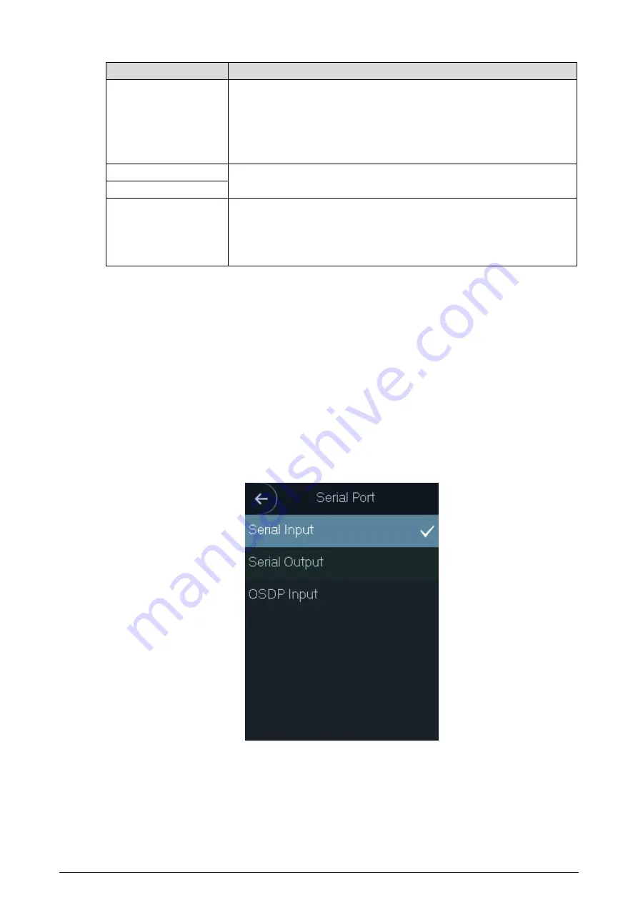
3.8.4 Serial Port Settings 

Select serial input or serial output according to the entering direction and exiting direction. 

Select 

Comm > Serial Port

 Serial port 

Figure 3-11


Select 

Serial Input

 when external devices that are with card reading and writing functions 

are connected to the standalone. 

Serial Input

  is selected to enable access card 

information to be sent to the standalone and the management platform. 


For  standalones  with  fingerprint recognition, card reading and writing  functions, if you 

select 

Serial Output

, standalone will send card number or user ID to the controller. 

Summary of Contents for Access Standalone

Page 1: ...Access Standalone User s Manual V1 0 1...

Page 2: ...rst release March 2020 V1 0 1 Add recommended installation height June 2020 About the Manual The manual is for reference only If there is inconsistency between the manual and the actual product the ac...

Page 3: ...l trademarks registered trademarks and the company names in the manual are the properties of their respective owners Please visit our website contact the supplier or customer service if there is any p...

Page 4: ...mation When replacing battery make sure the same model is used Use the recommended power cables in the region and conform to the rated power specification Use the power adapter provided with the stand...

Page 5: ...t the interference by one or more of the following measures Reorient or relocate the receiving antenna Increase the separation between the device and receiver Connect the device into an outlet on a ci...

Page 6: ...10 3 6 3 6 1 Adding New Users 10 3 6 2 Viewing User information 12 Access Management 12 3 7 3 7 1 Unlock Mode 12 3 7 2 Door Status 13 3 7 3 Lock Holding Time 14 3 7 4 Door Sensor Type 14 3 7 5 Remote...

Page 7: ...4 9 2 Port 37 4 9 3 P2P 38 Data Setting 39 4 10 Safety Management 39 4 11 4 11 1 IP Authority 39 4 11 2 System 40 4 11 3 User Management 40 4 11 4 Maintenance 41 4 11 5 Configuration Management 42 4 1...

Page 8: ...VII 6 2 8 Viewing Access Control Records 71 6 2 9 Viewing Device Logs 73 Cybersecurity Recommendations 75 Appendix 1...

Page 9: ...te unlock Support 30 000 users 30 000 cards and 3000 fingerprints Store 150 000 access records and 1000 alarm records Support duress alarm tamper alarm and report the alarm support 1 alarm input and 1...

Page 10: ...2 Back view mm inch Figure 1 2 Side and bottom view mm inch Figure 1 3 Table 1 1 Component description No Name 1 VA area 2 Doorbell button 3 Fingerprint sensor 4 Card swiping area 5 USB Port...

Page 11: ...allation Cable Connections 2 1 Cable connection Figure 2 1 Device Installation 2 2 The recommended installation height is 1 4 1 6 meters The standalone supports surface installation and concealed inst...

Page 12: ...n map on the wall and then drill holes according to hole positions on the Step 1 map Insert expansion bolt into installation holes Step 2 Fix the rear cover onto the wall with self tapping screws Step...

Page 13: ...oncealed installation Figure 2 3 Installation Procedure Draw the cables through the outlet Step 1 Fix the back cover on the mounted box with screws Step 2 Neaten the cables and buckle the front cover...

Page 14: ...he first page Go to the last page Go to the previous page Go to the next page Go to the previous menu Go to the next menu Initialization 3 2 Administrator password and an email should be set the first...

Page 15: ...er and special character excluding After the initialization is completed the standby interface is displayed Standby interface Figure 3 2 Standby Interface 3 3 You can unlock the door through fingerpri...

Page 16: ...nlock methods 4 Password unlock icon 5 Main menu icon Only the administrator can enter the main menu Unlocking Methods 3 4 You can unlock the door through card password fingerprint and the combination...

Page 17: ...administrator password for one standalone DSS Pro can issue 100 passwords for one standalone at most Administrator is not the password that was set during initialization Tap on the homepage Step 1 Tap...

Page 18: ...u Figure 3 5 User Management 3 6 You can add new users view user lists admin lists and modify the administrator password on the User interface 3 6 1 Adding New Users You can add new users by entering...

Page 19: ...th at most 32 characters including numbers symbols and letters FP Fingerprint registration Record the user s fingerprints Card Card registration Record the card information PWD The door unlocking pass...

Page 20: ...k the door there will be a delay of 5 seconds before the door is closed Use Time When the user level is Guest you can set the maximum number of times that the guest can unlock the door After you have...

Page 21: ...ns to unlock the door you can either swipe your card or get your fingerprints scanned Tap to save the settings Step 4 And then the Access interface is displayed Enable the Unlock Mode Step 5 means ena...

Page 22: ...n to set the effective time and then tap to enable it Remote verification is required when unlock doors To unlock the door a door unlock instruction sent by the management platform is needed means ena...

Page 23: ...configurations DHCP DHCP Dynamic Host Configuration Protocol When the DHCP is enabled the IP address can be automatically acquired and the IP address subnet mask and gateway IP address cannot be manua...

Page 24: ...ection and exiting direction Select Comm Wiegand and then the Wiegand interface is displayed Wiegand Figure 3 10 Select Wiegand Input when an external card swipe mechanism is connected to the standalo...

Page 25: ...number will be output 3 8 3 TCP Port The range is 1025 65535 and it is 37777 by default If you modify the port the system will restart automatically 3 8 4 Serial Port Settings Select serial input or s...

Page 26: ...mat setting date setting time setting and time zone settings 3 9 2 Volume Adjustment Tap or to adjust the volume 3 9 3 ScreenSaver Enable ScreenSaver the screen saver will be displayed if there is no...

Page 27: ...at execute like console applications running on a server that generates web pages dynamically When CGI is enabled CGI commands can be used The CGI is enabled by default SSH Secure Shell SSH is a crypt...

Page 28: ...to Factory Settings Data will be lost if you restore the access controller to the factory settings You can select whether to retain user information and logs Tap Default to restore the standalone to...

Page 29: ...date the program 3 10 1 USB Export You can export data from the standalone to the USB after inserting the USB The exported template is in xml format and you can edit user information and import it to...

Page 30: ...SB can be used to update the system Rename the updating file name to update bin and save the update bin file in the Step 1 root directory of the USB Select USB USB Update Step 2 The prompt Confirm to...

Page 31: ...rting Record You can search for and export all unlocking records System Information 3 11 You can search all unlocking records and view data capacity and device version of the standalone on the System...

Page 32: ...ation interface is displayed Use browser newer than IE 8 otherwise you might not log in to the web Initialization Figure 4 1 Enter the new password confirm password enter an email address and then tap...

Page 33: ...whether to select Auto Check Step 4 It is recommended that Auto Check be selected to get the latest program in time Click Next Step 5 The configuration is finished Finished configuration Figure 4 3 C...

Page 34: ...ssword after initializing the standalone Modify the password regularly and keep it properly for the sake of security If you forget the administrator login password you can click Forget password to res...

Page 35: ...e QR code on the interface and you will get the security code Step 3 At most two security codes will be generated by scanning the same QR code To get more security code refresh the QR code You need to...

Page 36: ...K and the reset is completed Step 7 Door Parameter 4 4 Set the door parameters including name state opening method hole time normally open time normally close time timeout and enable the alarms that m...

Page 37: ...Section During the selected period the door is normally closed And it is disabled by default Timeout Sec When the door opens longer than the configured time the overtime alarm will be triggered Enabl...

Page 38: ...played in the alarm log Alarm output and access link are NO by default if fire link is enabled Alarm Output Enable The relay can output alarm information will be sent to the management platform if the...

Page 39: ...alarm type and time range on the Alarm Log interface Select Alarm Linkage Alarm Log Step 1 The Alarm Log interface is displayed Alarm log Figure 4 10 Select a time range and alarm type and then click...

Page 40: ...e 4 13 Set the period number and time section name Select the Enable check box and the Step 3 time section as needed You can configure 128 periods weeks whose number range is 0 127 and set four period...

Page 41: ...ay group and then users cannot unlock the door in the periods that you have set Select Time Section Holiday Group Config Step 1 Holiday group configuration Figure 4 14 Click Add Step 2 Add holiday gro...

Page 42: ...s for holiday groups You can configure 128 groups whose number range is 0 127 You can add 16 holidays into a group 4 6 3 Holiday Plan Configuration You can add holiday groups into holiday plans and us...

Page 43: ...ble check box and then set the time section Click OK Step 4 Data Capacity 4 7 You can see how many users cards fingerprints alarm logs records admin logs and admin quantity the standalone can hold on...

Page 44: ...to configure IP address and DNS server to make sure that the standalone can communicate with other devices Precondition Make sure that the standalone is connected to the network correctly Select Netwo...

Page 45: ...be zero IP Address Enter IP address and then configure subnet mask and gateway address IP address and gateway address must be in the same network segment Subnet Mask Gateway Preferred DNS Server Set...

Page 46: ...etting Step 3 4 9 3 P2P Peer to peer computing or networking is a distributed application architecture that partitions tasks or workloads between peers Users can download mobile application by scannin...

Page 47: ...figure the following parameters You need to enable the NTP Check function first Server Enter the IP address of the time server and time of the standalone will be synchronized with the time server Port...

Page 48: ...ivacy Setting The system service configuration done on the web page and the configuration on the Privacy Setting interface of the standalone will be synchronized System service Figure 4 26 4 11 3 User...

Page 49: ...on the User Mgmt interface User management Figure 4 27 4 11 4 Maintenance You can make the standalone restart automatically in idle time to improve the running speed of the standalone Maintenance Fig...

Page 50: ...ndalone functions and improve stability If wrong upgrade file has been used the system will prompt that the upgrading fails and restart the device automatically Click Upgrade on the navigation bar Ste...

Page 51: ...ice 2 If there is any upgrade available click Upgrade and then the system starts upgrading Click Manual Check to check for upgrade manually 4 11 7 Version Information You can view information includin...

Page 52: ...ange type click Query and logs meet the conditions will be displayed 4 12 2 Backup Logs Click Backup to back up the logs displayed Admin Log 4 13 Enter Admin ID on the Admin Log interface click Query...

Page 53: ...45 Admin log Figure 4 33 Exit 4 14 Click click OK and then you will log out the web interface Hover over and then you can see detailed information of the current user...

Page 54: ...ne to the same network Step 1 Open the browser on the mobile phone enter the device IP address it is displayed on Step 2 the Wi Fi interface and 192 168 1 108 by default of the standalone in the addre...

Page 55: ...47 The homepage of the web is displayed...

Page 56: ...ccess permission to certain users or users in different door groups on DSS Pro Client For detailed operation see DSS Pro User s Manual Adding Devices 6 1 You need to add devise to the DSS Pro first so...

Page 57: ...49 Homepage Figure 6 2 On the homepage click Device Step 4 Device Figure 6 3 Click Add Step 5...

Page 58: ...ctual interface shall prevail When IP Address is selected you need to enter IP address of the device you are to add When Auto Register is selected you need to enter Registration ID of the device you a...

Page 59: ...ined automatically after Step 7 You can see the device you added on the Device interface If you want to add more devices click Continue to add Access Control Management 6 2 You can do door configurati...

Page 60: ...Homepage Figure 6 6 Click Access Control Step 2 On the left side of the interface right click an access control channel in the device tree Step 3 and select Door Configuration Access control Figure 6...

Page 61: ...an set a period during which the door is always open NC Period If enabled you can set a period during which the door is always closed Alarm Enable If the door is opened not as intended the door sensor...

Page 62: ...ck timeout triggers a timeout alarm Unlock Method You can use any one of the methods card fingerprint and password or any of their combinations to unlock the door Click OK Step 4 6 2 2 Creating Door G...

Page 63: ...edule Step 3 Select a channel and Click OK Step 4 Door group Figure 6 11 6 2 3 Issuing Access Cards You can issue access cards to people one by one or in batches On the Personnel Management interface...

Page 64: ...56 Authentication Figure 6 12 Click Edit and then click in Card section Step 2...

Page 65: ...57 Editing Figure 6 13 Select the card reader of the access standalone as needed Step 3...

Page 66: ...58 Reader manager Figure 6 14 Click Add next to Card and then put the card to the card reader to issue card Step 4 The card number is displayed...

Page 67: ...issuing cards to record fingerprints 6 2 4 First Card Unlock Only after the specified first card user swipes the card every day can other users unlock the door with their cards You can set up multiple...

Page 68: ...60 Advanced function Figure 6 16 Click the First Card Unlock tab Step 2 The First Card Unlock interface is displayed Click Add Step 3...

Page 69: ...s Parameter Description Door You can select the target access control channel to configure the first card unlock Time Template First Card Unlock is valid in the time period of the selected time templa...

Page 70: ...oor One group can have up to 50 users With Multi Card Unlock enabled for an access control channel it supports up to four groups of users being on site at the same time for verification The total numb...

Page 71: ...63 User group manager Figure 6 19 2 Click Add...

Page 72: ...ser Group Name Select users from User List and click OK You can select up to 64 users The system displays the user group information 4 Click in the upper right corner of the User Group Manager interfa...

Page 73: ...65 Multi card unlock configuration Figure 6 21 2 Select the door to configure Multi Card Unlock 3 Select the user group You can select up to four groups The system displays the user group information...

Page 74: ...to be on site and the Open Door Mode Click or to adjust the user sequence for each group to unlock the door The valid quantity refers to the number of users in each group that must be on site to swip...

Page 75: ...hat he or she came in from For the same person an entry record must pair with an exit record If someone has entered by tailing someone else which means there is no entry record this person cannot unlo...

Page 76: ...me You can customize the name of an anti passback rule Reset Time min The access card becomes invalid if an anti passback rule is violated The reset time is the invalidity duration When the selected d...

Page 77: ...when users unlock the doors with card fingerprint or password in the specified time period it must be confirmed on the platform client before the access controller can be opened On the Access Control...

Page 78: ...70 Add remote verification Figure 6 26 Select Time Template and access control channel and click OK Step 4 The system displays the remote verification information...

Page 79: ...added to the platform or were disconnected from the platform After the device is added to the platform or reconnects to the platform the platform will read the records generated when the device was o...

Page 80: ...separately On Access Control interface click Step 1 The Access Control Records interface is displayed Click at the upper right corner Step 2 The Password Verification interface is displayed Enter the...

Page 81: ...nd set period Step 4 Click to display devices and then select a channel Step 5 Click OK Step 6 The records are displayed 6 2 9 Viewing Device Logs View logs of access control devices such as login and...

Page 82: ...74 Device log Figure 6 30 Select a device and time and then click Search Step 2 The search results are displayed...

Page 83: ...s function to obtain timely information of firmware updates released by the manufacturer We suggest that you download and use the latest version of client software Nice to have recommendations to impr...

Page 84: ...TLS to access mailbox server FTP Choose SFTP and set up strong passwords AP hotspot Choose WPA2 PSK encryption mode and set up strong passwords 11 Audio and Video Encrypted Transmission If your audio...

Page 85: ...achieve the network isolation effect Establish the 802 1x access authentication system to reduce the risk of unauthorized access to private networks It is recommended that you enable your device s fir...

Reviews: