background image


11 

4.1  Cable Requirements 

The HDCVI PTZ requires the following minimum specifications for the coaxial cable used to transmit 

video: 


75 Ohm Resistance 


Full-cable with copper conductor 


95% knitted copper shield 

Transmission distances

1

 depend on the type of coaxial cable used and the maximum video resolution: 

RG-59/U Coax 

720p: 

500 m   (1640.42 ft) 

1080p:  400 m   (1312.34 ft) 
4 MP: 

300 m 

(984.25 ft) 

RG-6/U Coax 

720p: 

800 m   (2624.67 ft) 

1080p:  600 m   (1968.50 ft) 
4 MP: 

600 m   (1968.50 ft) 

CAT 6 UTP 
(balun required) 

720p: 

380 m   (1246.72 ft) 

1080p:  380 m   (1246.72 ft) 
4 MP: 

200 m 

(656.17 ft) 

4.2  Preparing for Installation 

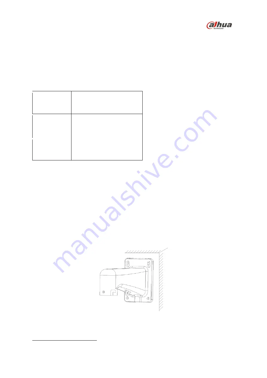
The HDCVI PTZ camera comes with the 64FB Wall Mount, the installer must supply the following 

hardware: 


Four (4) bolts, washers or other fastening hardware to secure the wall mount to the installation 

medium. The hardware must be capable of supporting eight (8) times the weight of the camera 

and mount. 


Appropriate tools to mount the camera to the wall. 

4.3  Mounting the Camera to a Wall 

1.  Remove the camera, the mount accessories, and any hardware packages from the boxes. 

2.  Place the 64FB Wall Mount against the wall and mark the location of the center hole and the four 

perimeter mounting holes. 


3.  Pre-drill the four perimeter holes as marked on the wall for the fasteners, using a drill bit that is no 

wider than the fastener.  

4.  Drill a 50-mm (approximately 2 in.) center hole to route the cables, if necessary.  


1

 Transmission distance results verified by real-scene testing in Dahua's test laboratory. Actual transmission distances may 

vary due to external influences, cable quality, and wiring structures. 

Summary of Contents for 6C430IC

Page 1: ...4 MP HDCVI PTZ Camera 6C430IC Quick Start Guide Version 001 001 Dahua Technology USA Inc...

Page 2: ...1 3 Legal Notices 4 Copyright 4 Trademarks 4 1 4 Disclaimer 5 2 Unpacking 6 2 1 Parts List 6 2 2 User supplied Tools and Hardware 6 3 Installation and Configuration 7 3 1 Framework and Dimensions 7 3...

Page 3: ...protect the unit from damage especially in damp environments Protect the plug and power cord from foot traffic being pinched and its exit from the unit Units with or without an ON OFF switch have pow...

Page 4: ...ng or installation Environmental Precautions Do not aim the unit at a strong light source or into direct sunlight to focus A strong light source may cause overexposure and may affect the longevity of...

Page 5: ...wipe a dome cover during installation this cover is an optical device Refer to the following methods clean the dome cover Stained with dirt Use an oil free soft brush or blower to gently remove the d...

Page 6: ...ee that interference will not occur in a particular installation If this equipment does cause harmful interference to radio or television reception which can be determined by turning the equipment off...

Page 7: ...y information Dahua accepts no liability for damage resulting directly or indirectly from faults incompleteness or discrepancies between this guide and the product described Dahua is not liable for an...

Page 8: ...er to transport the unit in the event the unit must be returned for service Retain the carton and all shipping material for future use Please refer to the enclosed CD for more details to view the deta...

Page 9: ...7 3 Installation and Configuration 3 1 Framework and Dimensions The following figures show the dimensions of the device in mm in These images are intended as a reference only Figure 3 1...

Page 10: ...D RS485 Yellow RS485 A Orange RS485 B 3 3 Alarm Setup Certain devices support alarm inputs and outputs check your specific device for alarm capability Alarm Input Refer to Figure 3 3 for alarm input c...

Page 11: ...external pull up level is 5 V and the maximum port current is 5 mA Once the output increases the pull up resistance the alarm decreases the output voltage to the normal state low level at less than 0...

Page 12: ...ing Install external interconnecting cables in accordance to NEC ANSI NFPA70 for US application and Canadian Electrical Code Part I CSA C22 1 for CAN application and in accordance to local country cod...

Page 13: ...Four 4 bolts washers or other fastening hardware to secure the wall mount to the installation medium The hardware must be capable of supporting eight 8 times the weight of the camera and mount Appropr...

Page 14: ...l the composite cable from the dome through the wall mount and pull it out of the other end of the wall mount bracket 8 Align the dome and the mount adapter so that the quick installation screw on the...

Page 15: ...er end of the safety hook to the anchor point on the 64FB Wall Mount Caution Make sure to attach the safety hook and ensure that it is securely fastened to the dome and to the wall mount to improve th...

Page 16: ...logy USA Inc 23 Hubble Irvine CA 92618 Tel 949 679 7777 Fax 949 679 5760 Email sales usa global dahuatech com Rev 001 001 2017 Dahua All rights reserved Design and specifications are subject to change...

Reviews: