


5
3 NVR Components
Check the label on the bottom of the NVR and note the model number and the power requirements
for this NVR. The label on the rear panel lists the serial number for the NVR. Please provide this serial
number when requesting information or service for this device.
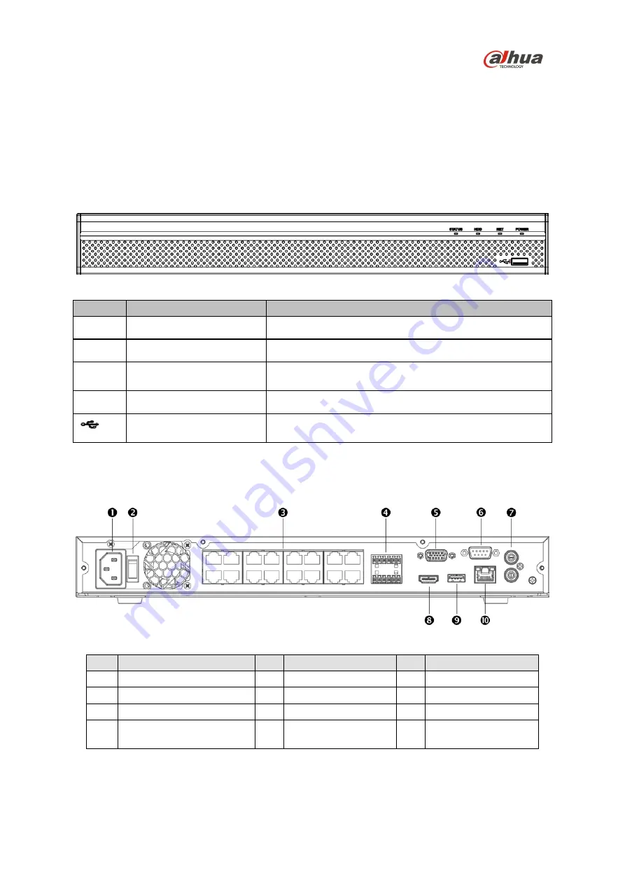
3.1 Front Panel
The figure below depicts the NVR front panel.
Figure 3-1
Light
Name
Function
STATUS
A blue light indicates the device is operating normally.
HDD
HDD status indicator
A blue light indicates that the HDD is malfunctioning.
NET
Network status indicator
A blue light indicates that the network connection is
abnormal.
POWER
Power status indicator
A blue light indicates that the power connection is OK.
USB 2.0 port
Connect to a peripheral USB 3.0 device (storage mouse,
CD/DVD burner).
3.2 Rear Panel
The image below is for reference only, it may not be an exact representation of your NVR. Please
refer to the Documentation CD that comes with the product.
Figure 3-2
Ref
Name
Ref Name
Ref Name
1
Power Input
5
VGA Output
9
USB 3.0 Port
2
On/Off Button
6
RS232 Port
10
RJ45 Port (1000 M)
3
PoE Ports (x16)
7
Audio Input/Output
4
Alarm Input/Output and
RS485 Connections (A/B)
8
HDMI Output


